
Assessing the Gate and Site Layout
Measuring the Gate Dimensions and Weight
A gate that swings freely by hand can still destroy a motor if the measurements are wrong. That is the uncomfortable truth facing every electric gate motor installation. The site layout deserves scrutiny before you commit to any equipment. Check the ground slope, the hinge condition, and whether the gate binds against anything during its arc.
Measuring the gate dimensions and weight demands precision. Record the leaf width, the opening height, and the total mass using a certified scale or the manufacturer’s data sheet. Keep these factors in mind:
- Leaf width determines the required motor arm length.
- Weight dictates the torque and drive mechanism.
- Pillar strength affects mounting stability.
Every number you capture here shapes the success of your electric gate motor installation. Record these details with care.
Identifying the Gate Type and Hinge System
A sliding gate and a swing gate are not interchangeable problems. Each requires a different motor family, and the hinge system on a swing gate will tell you a lot about the future of your electric gate motor installation. Worn hinge pins cause the leaf to sag, which drags on the ground and forces the motor to work harder than it should.
The gate type also dictates the operator. A cantilever sliding gate needs a rack and pinion drive, while a swing gate needs a linear arm or an underground unit. Inspect the hinge brackets for cracks and check whether the gate sits level when fully closed.
A good assessment covers these points:
- Gate type: swing or sliding
- Hinge pin wear and pivot corrosion
- Post alignment and mounting surface condition
- Available space for motor arm travel
In practice, I have seen clean gates fail because nobody checked the hinge posts. Stop at this stage, and the rest of the electric gate motor installation runs smoother.
Checking for Potential Obstructions or Slopes
Topography is the first truth an installer faces. A slope changes the gate’s behaviour before power is applied. A falling driveway adds load to a sliding gate’s drive system, while a swing gate on an incline might pass its natural stop. I always walk the full arc of the gate, including the open position.
The gradient affects arm travel too. The motor must work against gravity in both directions. Hidden obstacles appear only when the gate actually moves. Look beyond the obvious:
- Low branches or fence tension wires crossing the path
- Raised paving or curbs near the pivot
- Stormwater channels cutting across the run
- Long grass or shrubs blocking the opening
A competent electric gate motor installation depends on this honesty. Many callbacks trace back to a slope or an obstruction that someone ignored. An electric gate motor installation fails at the specification stage, not at the wiring stage.
Determining Power Source Proximity and Load Capacity
The shortest distance between two points is rarely the cable run you mapped out. Site layout dictates your electric gate motor installation more than any brochure will. I look at where the motor mounts, where the gate rests when open, and where a technician will kneel when everything stops on a Friday afternoon.
Power source proximity determines more than placement. A gate motor needs 220V without a voltage drop that turns a smooth operator into a sluggish grumbler. I measure the distance from the distribution board and check the wire gauge for the run. I also confirm the circuit is dedicated, because sharing a breaker with a geyser invites nuisance trips.
- Distance from the distribution board to the motor
- Wire gauge and voltage drop over the cable length
- Independent circuit with surge protection
Load capacity is where the brochure stops being helpful. The motor’s duty cycle and ingression protection class must match the gate’s actual weight, track friction, and daily opening frequency. An undersized unit for your electric gate motor installation will remind you of that decision every time it struggles.
Tools, Components, and Safety Preparation
Required Hand and Power Tools
South Africa sees thousands of gate motor failures each year, and most trace back to poor preparation. Before you start any electric gate motor installation, assemble a professional toolkit.
Your hand and power tools should cover cutting, fastening, and measuring:
- Angle grinder with a metal cutting disc
- Heavy duty drill and masonry bits
- Combination spanners and socket set
- Multimeter for electrical testing
- Wire strippers and crimping tool
Components are just as critical. Inspect the rack, mounting brackets, limit switches, and safety beams before you begin. Missing parts will stall the job halfway. For safety, isolate the power supply at the distribution board. Wear gloves and eye protection. Check that no buried cables sit behind your drilling points.
Choosing the Correct Motor Kit and Rack Size
Choosing the correct motor kit and rack size often determines whether an electric gate motor installation works reliably. A kit rated for a lighter gate strains on a heavy steel gate. The rack must match the motor’s pinion gear in module and pitch. If the rack sits too high or low, the gears bind.
Check the duty cycle. Industrial motors handle continuous use, while domestic units need rest periods. South African weather, dust, and load shedding affect performance. A surge protector is worth the expense. I have seen mismatched racks cause more failures than motor faults.
For the rack, measure the gate’s travel and add centimetres for the limit switch run. Stainless steel racks outlast galvanised options in coastal areas. When you plan a domestic electric gate motor installation, verify the limit switches are adjustable.
- Confirm the rack module matches the pinion gear
- Check the kit includes mounting brackets and limit switches
- Verify the motor’s force rating against the gate weight
Inspecting Concrete bases and Mounting Points
Before you trust a bracket to hold your gate’s momentum, inspect the concrete base like it owes you money. A crumbling edge or a hairline crack will turn a proud electric gate motor installation into a jackhammer impersonation. Tap the surface with a spanner. A dull thud means sound concrete; a hollow ring suggests voids that will shift your mounting points.
- Test anchor bolt tightness with a socket wrench
- Look for spalling or efflorescence around the base
- Ensure the base protrudes at least 10 cm above ground level
Check the anchor bolts for rust and torque. Use a spirit level on the column. Something that looks plumb can still be off by a few degrees, which matters when the rack has to align with the pinion. In South Africa, thermal expansion and load shedding add their own quirks. A square base today might be a parallelogram by next summer.
Personal Protective Equipment and Electrical Isolation
Some statistics claim that over 75% of South African homes have experienced a power surge during load shedding. Your electric gate motor installation process must treat electricity as a living threat, not a utility. The headline is safety preparation.
Before a single spanner touches a terminal, the power must be dead. This rule is absolute. Your Personal Protective Equipment includes safety glasses and insulated gloves with a Class 0 rating. These gloves are not for comfort. They are the only barrier between you and a circuit that might be energised by a poorly managed inverter or a neighbour’s illegal connection.
Check the test button on your circuit breaker. A tripped breaker might not mean a de-energised line, especially with backup systems in play. Use a non-contact voltage tester to verify the feed. Then, lock the isolator switch with a padlock. This creates a physical barrier against accidental activation. Electrical isolation is a deliberate ritual. Pull the fuse, test the supply, and then test again. Apply a warning tag to the visible switchgear. The electric gate motor installation demands this discipline, because Eskom rarely gives a warning before returning power.
For the components, organise your rack, pinion, and limit switches in a clean work area. A dedicated workspace prevents accidental damage to the motor’s control board. Check the torque settings on your drill before you touch the column. A slipping clutch can strip a mounting bolt and ruin the alignment you checked earlier. Keep your socket set calibrated within factory tolerance. Everything else, including the gate’s mechanical lock, depends on this precision.
Motor Mounting and Mechanical Drive Setup
Positioning and anchoring the Motor Bracket
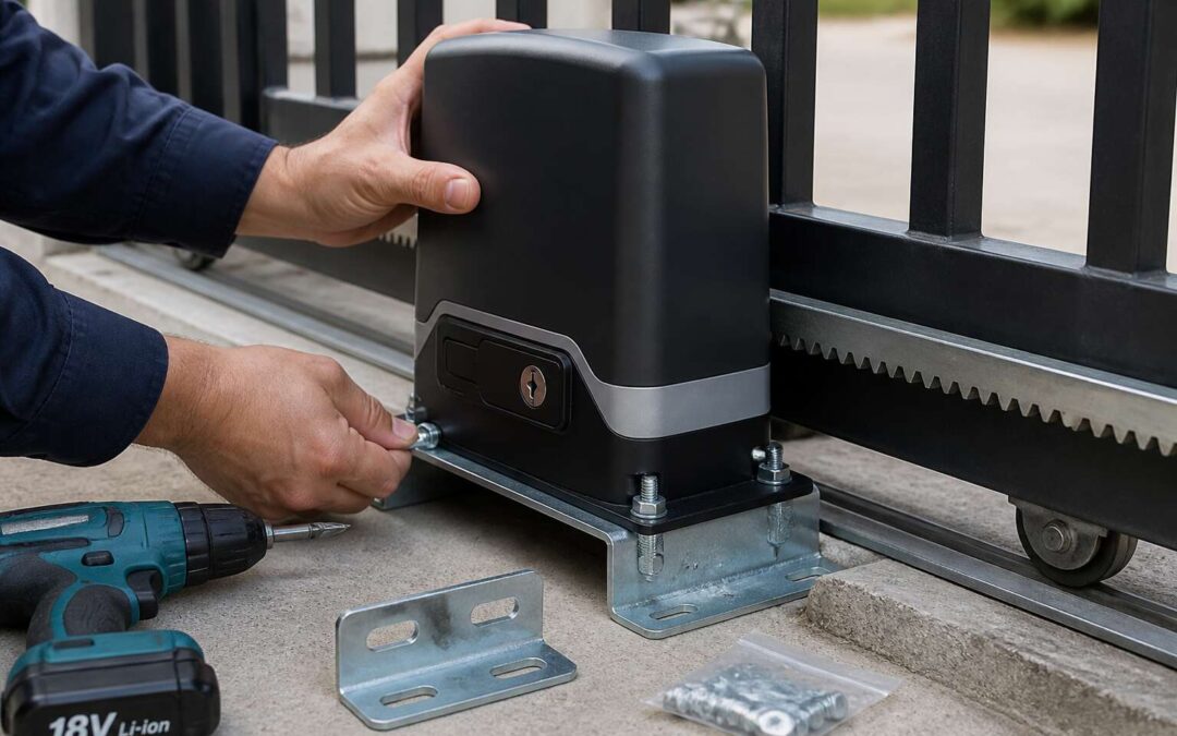
Positioning the motor bracket is where many installations meet their end. The concrete base may be perfect, the gate balanced, yet a misaligned bracket introduces strain that shortens motor life. Place the rack on the gate first, then fit the motor. This sequence reveals the true contact point. The bracket height must match the pinion gear to the rack with a specific clearance. South African heat can warp materials that sit too close. A gap of two to three millimetres usually suffices.
Anchoring demands absolute rigidity. Loose bolts invite chatter and misalignment during operation. Use high tensile fasteners rated for outdoor exposure. The bracket must resist the torque generated when the gate starts and stops. A motor that rocks in its mount will strip gears over time. Ensure the bracket sits flush against the concrete. Shim the base where needed with steel plates.
Check the bracket alignment across all planes:
– Vertical plumb against the gate leaf
– Horizontal level across the mounting plate
– Parallel to the rack travel path
Then tighten the anchor bolts diagonally, in stages. This prevents the bracket from pulling sideways. An electric gate motor installation lives or dies by this preparation. A few minutes spent here saves hours of troubleshooting later. The motor should sit on a solid, level plane. Uneven tension on the mounting plate creates angles that cause the rack to bind. That binding translates into false obstruction signals and premature wear. Take the time to ensure the bracket is true.
Aligning the Drive Pinion With Gate Rack
The moment of truth arrives when the motor meets the rack. Many assume mounting the unit completes the task, yet this phase determines whether the system thrives or fails silently. The pinion gear must sit flush against the rack teeth, not merely close enough to catch occasionally. Mesh depth of less than sixty percent invites slippage under load, a common failure in South African installations where heat expands metal components unevenly.
Proper alignment requires patience. The motor should rest on its bracket while you rotate the gate by hand. Watch how the pinion interacts with the rack through a full travel cycle. Any skip or hesitation indicates a height discrepancy. You want the gears to engage with a slight backlash, typically one to two millimetres between teeth. Too tight creates binding, too loose produces that metallic chatter heard across suburban yards.
– Check pinion height against the rack’s neutral axis
– Verify the motor’s mounting plate sits perfectly perpendicular
– Test engagement across the full gate path
– Listen for abnormal sounds during manual operation
The relationship between these components carries the entire operational burden. Electric gate motor installation demands this precision because torque multiplies through the drive train. A motor working against misaligned gears draws excess current, overheating windings and tripping thermal overloads. The drive pinion should sit at the exact centre height of the rack, never above or below. Even a three millimetre error concentrates force on a contact point, wearing teeth into rounded stubs within months.
Securing the rack and Adjusting Gear Clearance
When it comes to electric gate motor installation, the mounting phase often feels like the finish line, but it is really just the starting point. After you have measured, inspected, and positioned the bracket, the real work begins with anchoring the motor securely. A motor that sits loosely on its bracket will shift every time the gate moves, and that constant micro-movement wears out the gearbox faster than you might expect. In South Africa, where afternoon heat can cause steel to expand and contract, a solid mount is not a luxury; it is a necessity. Use heavy-duty bolts, and always check that the mounting surface is perfectly level before you tighten anything down.
Once the motor is fixed, you need to turn your attention to the mechanical drive setup. This is where the rack and pinion come into play. The rack, which is usually bolted to the gate itself, has to run parallel to the gate’s travel path. If it veers even a few millimetres off course, the pinion gear will struggle to maintain contact, and that leads to uneven wear and jerky motion. I have seen countless installations where the rack was installed with the teeth facing the wrong way or at a slight angle, and the result is always the same: premature failure. Take your time to measure the gap between the rack and the pinion across the entire length of travel, not just at one point.
Securing the rack is a straightforward task, but it demands attention to detail. You want to use bracket supports every 400 to 500 millimetres along the gate, especially for longer spans. This prevents the rack from sagging or flexing under load. In many South African homes, gates are made from mild steel or aluminium, and the rack will need to be welded or bolted depending on the material. Bolting is easier to adjust later, but welding offers a more permanent fix. Whichever method you choose, make sure the rack is firmly attached and does not move independently of the gate. A rack that rattles will eventually strip its teeth, and that is a costly repair.
Now for the part that most installers rush, adjusting the gear clearance. This is the distance between the pinion gear and the rack teeth. Too much clearance and the gears will slip, causing the gate to judder or stop mid-travel. Too little clearance and the gears will bind, putting extra strain on the motor and drawing excessive current. The sweet spot is a small backlash, usually around 1 to 2 millimetres of play. You can feel this by rocking the gate back and forth by hand; there should be a slight click, not a loose rattle or a stiff resistance. Proper clearance also reduces noise, which matters when your gate runs right next to a bedroom window.
A helpful way to approach the entire process is to follow a simple sequence. Start by mounting the motor and checking its alignment with the rack. Then secure the rack properly, ensuring it is straight and level. Finally, adjust the gear clearance and test the gate manually before you connect power. I often tell clients to run the gate up and down a few times by hand before switching on the motor. That simple check reveals any binding or scraping that would otherwise damage the system within days. Remember, electric gate motor installation is not just about bolting things together; it is about setting up a harmonious mechanical relationship that will last for years. Take the extra ten minutes to get the clearance right, and you will avoid the headaches of callbacks and warranty claims. A well-adjusted gate moves smoothly, quietly, and efficiently, which is exactly what you want in the South African climate, whether you are in Johannesburg or Durban.
Installing Manual Release and Idler Rollers
It’s easy to think of the mechanical drive as the only story, but the manual release is the quiet hero of any electric gate motor installation. If the power vanishes, and it will in South Africa, the gate still needs to function as a manual barrier. The release mechanism, usually a key or lever on the motor housing, disengages the gearbox. This allows the gate to slide freely by hand. If this step is stiff or poorly adjusted, you will be wrestling with a 200-kilogram steel door during a load-shedding blackout. Lubricate the release lever and test its motion before you finish the job. A gate stuck in the closed position is a security problem, but a gate stuck open is an invitation.
Idler rollers are another component that installers often treat as an afterthought. These rollers support the gate on its track, and they prevent the weight of the gate from pulling the rack away from the pinion. Without proper idler support, especially on a cantilever or sliding gate that runs longer than five meters, the rack will flex. This flexing translates directly to the gear clearance, which you just spent time adjusting. You will need to place the rollers at the leading and trailing edges of the gate, not just in the middle. One critical point to remember is that these rollers must be adjustable. You need the ability to fine-tune the vertical and horizontal pressure on the gate, otherwise the gate will bounce on the track every time it passes over a joint.
Here is a quick sequence that installers often ignore but makes the process effortless:
1. Mount the manual release bracket so it is accessible at a comfortable height.
2. Install the idler rollers before you tighten the motor mount fully.
3. Check that the rollers contact the gate’s guide channel along the full travel path.
4. Adjust the roller tension so the gate moves without lifting off its track.
The rollers should spin freely, but the gate should not wobble when you push it. If you hear a metallic scraping sound during a manual test, the rollers are misaligned. Remember, the entire system is interdependent. A well-anchored motor means nothing if the gate sags onto the track. And a perfect gear clearance is useless if the gate swings out of alignment on a weak idler. For South African installations, where the wind can catch a gate like a sail, these mechanical supports are what keep the system honest. Take the extra time to tune them, and the motor will work far less hard.
Checking Runtime Alignment and Lubrication Points
Runtime alignment proves the installation. After mounting and clearance adjustments, power the motor and run the gate through full travel. Watch for hesitation or grinding. If the gate moves smoothly by hand but struggles under motor power, alignment is off. Recheck pinion depth and track level.
Lubrication points dictate long-term reliability. The rack, pinion, bearings, and manual release mechanism need specific attention. Use light lithium grease on the rack, penetrating oil on pivots. Never over-grease near the motor housing, as it attracts dust.
- Rack and pinion: thin lithium grease layer.
- Roller bearings: one drop of light machine oil.
- Manual release lever: lubricate pivot and lock cylinder.
An electric gate motor installation in South Africa faces dust and wind, so regular lubrication prevents silent degradation and motor overload failures.
Wiring, Control Connections, and Safety Devices
Running Conduit and Cable Routing
Most electric gate motor installation faults trace back to sloppy wiring. Power craving connections and exposed cables invite corrosion, especially in South Africa’s dusty and rainy regions. Get the fundamentals right or the system will fail prematurely.
Control connections need restraint. Keep low Pauline voltage lines separate from mains carrying conductors. Use stranded wire for flexing sections. Verify the limit switches and safety edges receive solid terminations. Loose screws cause ghost triggers and randomized gate behavior.
- Run conduit from the motor housing to each safety device.
- Secure all junction boxes away from standing water.
- Label every cable for future fault tracing.
Cable routing demands planning. Bury conduit deep enough to avoid spade strikes. Avoid sharp bends where insulation wears thin. Leave service loops at both ends. That allows motor removal without cutting wires. Sound routing extends the installer’s grace period. Choose direct burial rating only if the soil permits. Otherwise, steel armored conduit shines. Measure twice, pull once, test always.
Connecting Power Supply and Transformer
The transformer is where many electric gate motor installation faults reveal their true colors. A mismatch between the supply voltage and the motor’s requirement causes sluggish movement or total silence. South African grid variances make this a real pain, so verify the input and output ratings before connecting anything.
Control wiring deserves the same attention. Keep the low voltage safety loop separate from the mains feed, and use stranded wire for the moving sections. Solid terminations on the limit switches and safety edges prevent ghost triggers.
- Check the transformer’s VA rating against the motor’s peak draw.
- Confirm the earth leakage isolator is rated for the inrush current.
Every terminal screw should bite copper, not insulation. Loose connections here will make the gate dance unpredictably.
Wiring the Control Board, Receiver, and Keypad
Connecting the control board transforms your electric gate motor installation into a thinking machine. This is where the receiver, keypad, and safety devices form a nervous system. Each wire acts as a signal, dictating movement and response. Before you energise the system, assign each terminal its purpose. Most boards feature labelled ports for open, close, and stop commands. Use the common negative terminal for the receiver and keypad returns. This prevents stray voltage potential from creating phantom signals.
The receiver needs a clean power source from the board’s 12V or 24V output. Avoid sharing this feed with the motor drive wires. A surge here does more than trip a fuse, it corrupts the radio frequency memory. For the keypad, keep the data wire twisted with its ground return to reduce interference from the gate’s motor feedback. This is a non-negotiable practice for reliable long distance performance.
– Verify the receiver’s relay output is set for momentary pulse, not latching.
– Connect the keypad’s request to exit input directly to the open command.
– Use shielded cable for the safety edge and photo beam signals.
The safety loop earns its keep during power outages in South Africa. Connect the battery backup terminals precisely, as polarity errors here will fry the board’s charging circuit. The limit switches should use normally closed contacts. This ensures a wire break halts the gate, rather than causing an unpredictable stop. Secure the earth strap to the control board’s exposed metal grounded lug. The entire electric gate motor installation relies on this final connection to behave safely under surge conditions.
Attaching Limit Switches and Encoders
Attaching limit switches and encoders demands precision. The limit switch tells the motor where travel ends, while the encoder tracks position and speed. Both depend on secure mounting and correct alignment. Get this wrong and the gate will punch through its mechanical stops!
Limit switches should use normally closed contacts. If a wire breaks, the gate halts rather than running wild. Mount the encoder directly on the motor shaft or the pinion shaft. In my experience, flexible couplings tend to introduce play, which corrupts position readings.
- Check switch cams against the gate’s full travel path.
- Keep encoder wiring separate from motor cables.
- Cycle the gate fully after attaching both devices.
For any electric gate motor installation in South Africa, the limit switches and encoder form a feedback loop that prevents over-travel and misalignment. Adjust them carefully and verify each terminal against the wiring diagram before restoring power.
Installing and Photographic Safety Edges
Automated gates depend entirely on the quality of their safety interlock. One aged cable or strained terminal can turn a routine motion into a destructive one. When handling electric gate motor installation, treat the control wiring and the safety devices as the nervous system of the entire unit. Keep all low voltage sensing lines separate from the motor power cables. Route them through distinct conduits, or cross them at ninety degrees, otherwise the induction from the motor can simulate a blocked photocell.
Wiring the control board demands familiarity with its terminals. I always attach a remote receiver, the keypad, and the safety devices using separate connector blocks instead of twisting wires together. Each safety input, including the photographic safety edge, should sit in a normally closed loop or a monitored channel. That way, the controller sees a jumper break, not an open safe state.
The photographic safety edge is an air chamber that collapses under pressure. It sends a resistance change to the control board. For reliability, install the edge, then cycle the gate and trigger the edge with your hand. Use a proper sequence:
- Mount the edge profiles to the leading surface of the gate blade.
- Connect the edge cable to the dedicated controller port.
- Programme the controller to reverse on contact.
- Test the edge with a concrete block at both leaf edges.
Electric gate motor installation with a faultless safety circuit is a question of tuning the sensor loop, not just trusting the equipment.
Grounding, overcurrent protection and Surge Protection
Grounding is the first line of defence. Without a proper earth spike, a fault can energise the entire gate frame. For electric gate motor installation, use a dedicated earth leakage relay and bond the motor chassis to the main earth bar. Overcurrent protection matters too. Each motor circuit needs a correctly rated breaker, matched to the inrush current.
Surge protection is equally critical. South African thunderstorms can send spikes down the supply line. Fit a surge arrestor at the distribution board and a secondary unit near the controller. For control connections, keep all safety device wiring on isolated earths.
- Check earth loop resistance before commissioning.
- Never fuse safety circuits above the manufacturer’s spec.
Testing, Calibration, and Final Adjustments
Performing the Initial Open and Close Cycle
The moment of truth arrives with the first press of the button. After all the measuring, wiring, and mounting, your electric gate motor installation finally meets its first task. Watch closely, as the initial cycle reveals every hidden flaw.
Observe the full travel without interruption. Sudden stops, grinding noises, or a gate that lurches forward demand immediate attention. Calibration corrects these hesitations. For a solid read on the system, check these items during the cycle:
- Constant speed throughout the travel path.
- Clean disengagement at the limit switches.
Only when the cycle completes flawlessly does the tension subside. A smooth initial run under South African conditions confirms your setup is correctly tuned. You can then disconnect the tester without panic.
Fine-tuning Force Limits and Auto-Reverse
The initial run is done, but the real work begins with force limits and auto-reverse. Every electric gate motor installation needs these dialed in precisely. If the gate meets resistance, the reversal must trigger instantly. I test with a solid object, not a soft bag, to avoid false confidence.
Calibrate the force on both open and close directions independently. A gate that struggles in one direction will burn out the motor. Use the manufacturer’s procedure to set torque. Then verify auto-reverse by placing an obstruction mid-travel.
- Check the reversal distance: it should stop within 30 mm of contact.
- Confirm the gate reopens fully after reversing.
Adjust force limits in small increments. The gate should stop without slamming, yet handle a stiff breeze. South African winds demand this balance. After each tweak, run three cycles. Then the electric gate motor installation is ready for daily service.
Programming Remote Controls and Operation Styles
A remote that works at two metres and fails at ten is never a signal problem. It is a receiver placement issue or a drained transmitter battery, and both are preventable. Before pairing anything, clear the receiver memory to purge stray codes from previous tenants or lost fobs. I always pair each transmitter individually, then walk the property boundary to confirm range.
Operation styles should be decided during the electric gate motor installation, not weeks later when the client has misplaced the manual. Choose the logic that matches the property, and write the settings inside the control box lid!
- Auto-close for commercial sites where gates must never linger.
- Hold-to-run for homes with children or pets near the track.
- Pedestrian mode for partial openings that keep the main gate secure.
After programming, test every button, including the pause and emergency release. The gate must stop instantly when commanded, and the remote battery should be labelled with its install date. This final sweep prevents callbacks and confirms the electric gate motor installation is complete.
Handover and Ongoing Maintenance Guidance
Creating a Routine Cleaning and Lubrication Schedule
The handover is the most important stage of the service. I walk the client through the manual release and the chain pairing. The electric gate installation is complete, but the client still needs guidance for future care. Explicit steps now prevent frustration alone.
Ongoing maintenance demands a repeatable schedule. Create a weekly cleaning routine to stop grit from binding the pinion. Use a dry cloth to remove dust from the track. Apply a silicone spray to the rack and gear once a month. Keep all lubricant off the tread and the motor housing. This straightforward care preserves a smooth open and close cycle.
For the following checkpoints, make a habit of this flow.
- Remove leaves and loose particles from the bottom runner.
- Spray the chain tensioner with an anti climate conditioner.
- Confirm the limit switch bolts seat firmly against the cam.
Recommending Safety Inspection for Entrapment Protection
Handover becomes meaningful when the safety inspection for entrapment protection takes precedence. I place a rolled towel in the gate’s path and ask the client to observe the reversal. This direct check confirms the force settings align with South African regulations.
- Examine the safety edge for cuts or kinks.
- Verify the photocell lenses stay clean and aligned.
- Test the auto-reverse feature every month.
Ongoing maintenance should repeat these checks without fail. The electric gate motor installation protects property, while the entrapment sensors protect people. A delayed reversal or a silent safety edge demands immediate professional intervention.
Troubleshooting Common Symptoms
Handover is where the true measure of a successful electric gate motor installation comes to light. It is not merely about handing over a remote and a set of keys. A proper handover is a working session where you walk the client through the operational nuances of their specific system. This includes demonstrating the manual release procedure during a power outage, which is a critical feature often overlooked until an emergency occurs. You must also clarify the limits of the warranty and provide a clear, written maintenance schedule. This step prevents the all-too-common scenario where a minor user error is mistaken for a mechanical failure. When the client understands the system’s rhythm, you significantly reduce unnecessary callbacks and build a foundation of trust.
Ongoing maintenance is the heartbeat of longevity for any automated gate. South African weather, with its intense UV rays and seasonal downpours, can be brutal on rubber seals and steel components. A proactive approach involves a bi-annual check of the entire system. This is where you physically inspect the limit switches for corrosion, verify that the gearbox oil level is within spec, and tighten any bolts that may have vibrated loose from frequent use. The battery, often the silent hero of the system, needs a voltage test to ensure it can still deliver a full cycle of opens and closes without mains power. These tasks are not optional extras; they are the difference between a gate that lasts a decade and one that fails within three years.
Even with a flawless installation, symptoms of wear will eventually surface. The most common complaint is a gate that hesitates or stops midway. This often points to a struggling gearbox, a misaligned rack, or an obstruction sensor that has shifted slightly from its original position. Another frequent issue is a remote that works intermittently, which usually signals a weak battery or a signal interference source newly introduced to the property. Rather than guessing, a systematic approach is best. Consider this troubleshooting flow:
– Check the primary power source; is the mains breaker tripped?
– Inspect the photo beams for any spider webs or dirt blocking the line of sight.
– Test the battery voltage under load; a reading below 12 volts often indicates a replacement is due.
– Listen to the motor; a grinding noise suggests a gear wear issue, not an electrical one.
By following this sequence, you often resolve the issue without replacing expensive parts. It is about understanding the relationship between the mechanical and electrical components.
Ultimately, the goal of this post-installation phase is to demystify the technology for the homeowner. They need to feel empowered to perform simple visual checks, like confirming the safety edges are intact and the gate path is clear of debris. This shifts the narrative from a complex repair job to a manageable routine. When you equip the owner with the knowledge of what to look for, you are not just selling a product; you are providing a reliable, secure entry point to their home. A well-documented handover and a clear maintenance plan turn a simple motor into a long-term asset. This is the final, and most crucial, layer of a professional electric gate motor installation that prioritises safety and durability above all else.
Preparing for Extreme Weather and Power Outages
Power cuts have become a fixture of South African life, and they expose the weak points of any automated system. A proper handover for your electric gate motor installation must include a live demonstration of the manual release procedure. You cannot simply point to the lever and hope for the best. Show the client how to disengage the motor and how to re-engage it after the mains power returns. This single action prevents a homeowner from being locked out during a scheduled outage or a cable theft incident.
Ongoing maintenance is your shield against the elements. The highveld sun and coastal salt air will attack the system’s components. A bi-annual service should focus on the battery condition, which is your only line of defence during a blackout. Ensure the gearbox seals are intact and that the limit switch housings are free of moisture. To prepare for severe storms, verify the surge protection is still functional after any lightning activity. A structured approach includes:
– Test the battery voltage under a simulated load to confirm it can complete a full open and close cycle.
– Inspect all rubber gaiters and seals for cracks caused by UV degradation.
– Confirm the manual release handle moves freely and does not stick from rust.
The goal is to ensure the system reacts predictably when the grid fails. You must also explain how the gate behaves when the backup battery is depleted. Does it fail to a locked state or an unlocked state? The client needs to know this before they are standing in the rain. By preparing for these specific weather and power scenarios, you transform a standard electric gate motor installation into a dependable security feature. The handover is not the end of the process; it is the start of a relationship built on clear expectations.