
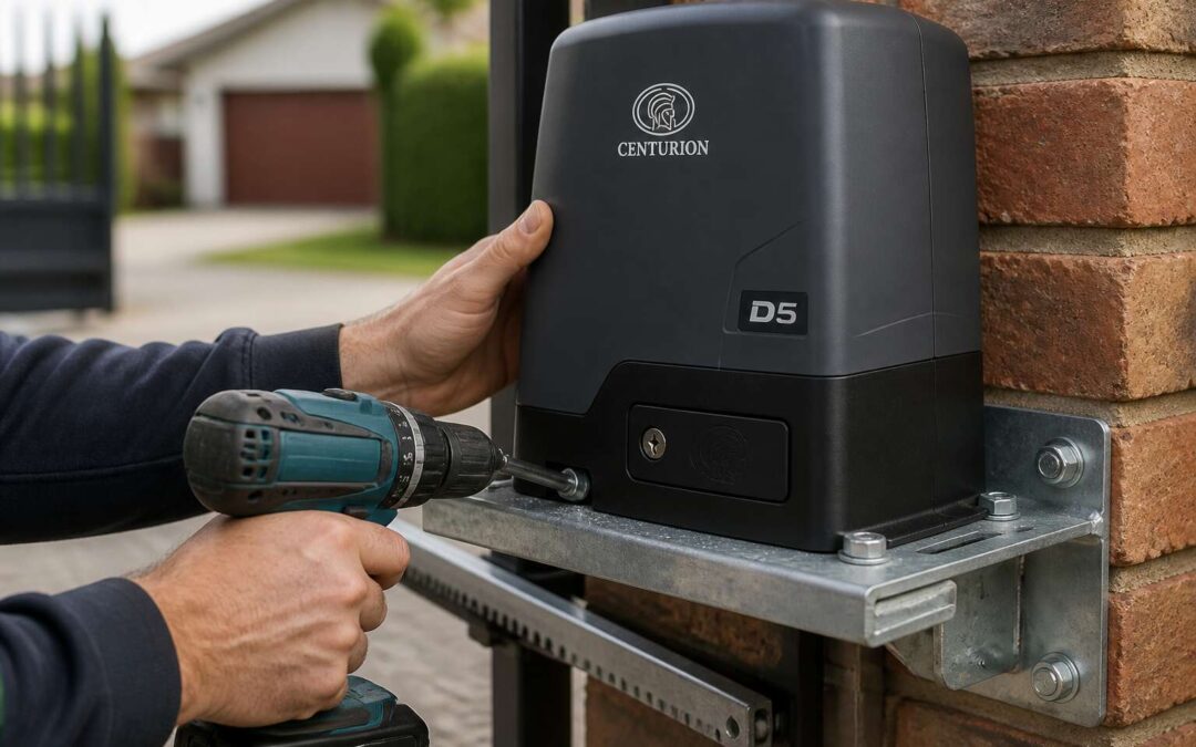
Planning Your D5 Gate Motor Setup
Assessing Gate Type, Weight, and Travel Distance
Before any d5 gate motor installation begins, the physical realities of your gate demand scrutiny. A sliding gate behaves differently from a swing gate, and each presents unique load characteristics. Weight matters enormously. A gate that moves freely by hand can still strain a motor once friction, wind, and wear enter the equation. Travel distance determines the gear ratio and limit switch settings, so measure it precisely.
I’ve seen too many setups fail because these basics were skipped. Consider these factors when assessing your setup:
- Gate type: sliding or swing, plus the condition of its track or hinges
- Weight: including decorative cladding or future additions
- Travel distance: the full arc or linear path the gate must cover
These measurements inform every subsequent decision in the installation process.
Confirming Power Supply and Voltage Requirements
Every d5 gate motor installation begins with a question that has nothing to do with the gate itself: what power will feed it? Voltage mismatches destroy automated systems. A motor rated for 220V that meets 110V will struggle. Feed 380V into a domestic unit and the smoke follows. Confirm the supply at the gate, not at the distribution board, because voltage sags under load.
Battery backup matters in South Africa. Interruptions are common, so the control board must maintain closure on reserve power. Check the charger output, the battery age, and the earth leakage protection.
- Verify the motor’s nominal voltage against the installed supply
- Confirm the load of any auxiliary lighting or intercoms
- Measure the current at peak gate movement
Each step protects the board from erratic behaviour, ensuring the mechanism answers only when commanded. A d5 gate motor installation depends on this electrical diligence.
Gathering Permits and Reading Local Safety Codes
Before any concrete is poured, the paperwork must be settled. I have seen homeowners skip the permit step because their neighbour did the same. That gamble rarely pays off! Municipalities across South Africa enforce bylaws for automated gates, and a d5 gate motor installation without approval can become a costly reversal.
Local safety codes dictate more than the motor placement. They specify the force limits on the gate leaf, the requirement for photo beams, and the clearance distances from public walkways. Reading these rules before you order parts stops you from undoing fresh work.
- Visit the municipal planning office or website for the exact application form.
- Confirm whether a licensed electrician must sign off the d5 gate motor installation.
- Check if the property is in a heritage area with stricter visual restrictions.
Permits take days, not hours. Factor that delay into your schedule and you avoid the late penalty fees that some councils impose without warning.
Creating a Pre-Installation Checklist
Nearly 40% of automated gate failures trace back to poor planning. A d5 gate motor installation demands more than a solid concrete footing and a charged battery. Concrete needs curing time. Cables need conduit. Brackets need alignment. Skip the order and you will redo the job twice.
Before mixing cement, I always walk the full gate travel path. Look for obstructions, drainage channels, and uneven ground that could shift the track. Mark where the motor bracket will sit and confirm the gate opens without binding.
Create a pre-installation checklist covering the physical layout:
- Measure the clearance between the gate leaf and the boundary wall at full open and close.
- Locate underground pipes or conduit near the anchor area.
- Confirm the manual release is accessible from both sides.
- Check the wheels and track before adding motorised force.
Each item protects your budget. A d5 gate motor installation done right starts with a clear plan, not a rushed dig.
Essential Tools, Parts, and Accessories
Full List of Tools Needed for Mounting and Wiring
A d5 gate motor installation is only as smooth as the tools you marshal for the job, and improvisation during mounting and wiring will cost you a Saturday. You need a decent hammer drill with a 10mm masonry bit for the anchor bolts, plus a socket set and a calibrated torque wrench for the rack and bracket fixings. A multimeter is non-negotiable for verifying the 24V supply before you connect anything; electricity is unforgiving, but it is also predictable.
Keep the smaller implements organized and close at hand:
– A flathead and Phillips screwdriver for the limit switches and terminal blocks
– Wire strippers and a crimping tool for the motor cable and photo beam wiring
– A spirit level, because a gate that drifts looks like a mistake, not a feature
– Cable ties and a sharp utility knife for tidying the loom without nicking the insulation
Gather all of this before you start. Racing back and forth for a lost 13mm spanner mid-installation turns a straightforward d5 gate motor installation into a small existential crisis, and nobody needs that level of drama in their driveway.
Identifying Included Components vs. Optional Kits
Open the box and you will find the motor unit, a handful of bolts, and a rack that somehow looks longer on the diagram. The d5 gate motor installation typically includes the controller, two remotes, and the rack. What it does not include is the photo beams, the keypad, or the backup battery. Those live in the optional kits, sold separately because gate automation is also the art of the upsell.
Before you start mounting, separate the included components from the optional ones. A quick inventory helps.
- Confirm the rack length covers the gate travel.
- Check the bracket pack for grade 8.8 bolts.
- Set aside the limit stop lugs before wiring.
Optional kits add convenience but not structural support. Order them early if you want them.
Selecting Proper Brackets, Racks, and Safety Accessories
Mounting a motor correctly matters less than matching the hardware to the environment. A d5 gate motor installation on a coastal property demands stainless steel brackets; inland, grade 8.8 zinc-plated bolts hold up fine. The rack must sit parallel to the gate rails, so measure the sprocket height before cutting. Safety accessories, especially photo beams, need a clear line across the full opening. Their mounting brackets should allow vertical adjustment, because concrete settles and posts lean.
Consider the gate material. A heavy steel gate needs a rack welded or bolted at every 300 mm. Lighter aluminium gates allow longer gaps. Limit stop lugs should be clamped, never welded, until you test the reversal system. That way you can reposition them without grinding. A proper d5 gate motor installation also depends on the bracket spacing.
- Check the rack’s module matches the motor sprocket teeth.
- Confirm the bracket bolts clear the gate’s crossbracing.
- Choose photo beam brackets with slotted holes for fine tuning.
Skipping these checks will void your warranty faster than a lightning storm in Gauteng.
Step-by-Step Mechanical Installation of the D5 Operator
Positioning the Motor Bracket on the Pillar or Post
The pillar is the anchor of your entire gate system, and the D5 gate motor installation begins with placing its bracket with surgical precision. If the steel support is skewed or bolted to a hollow brick facade, the motor will fight itself at every revolution, shaving years off its lifespan before the first rainy season in Johannesburg or Cape Town.
You want the bracket face perfectly perpendicular to the gate track. Use a laser level across the mounting holes, or a spirit level if the light is failing. The operator’s output shaft must align with the rack height on the gate leaf. A mismatch of 5 millimetres creates grinding chatter and premature wear on the pinion teeth. The pillar itself must be dense enough to hold the expansion bolts. If you suspect hollow construction, switch to chemical anchors.
Here is what to check before you pull the trigger on the drill:
– The bracket’s base plate sits flush against the pillar, no rock or wobble.
– The motor’s pivot arm clears the gate’s hinge brackets when fully open.
– The mounting height allows the rack to pass under the pinion without fouling.
Once you lock down the bracket, hand-tighten the bolts first, then apply final torque in a cross pattern. You want the bracket to settle into the surface, absorbing the violent rebound forces when the gate slams against the limit switch. This is not a place for guesswork. A poorly set bracket turns every daily open and close cycle into a slow demolition of your own driveway.
Attaching the Rack and Pinion for Smooth Travel
For a smooth d5 gate motor installation, the rack’s alignment governs everything. I slide the pinion into mesh first, then feed the rack beneath it. The teeth must meet with consistent pressure. I measure the backlash using a feeler gauge, aiming for a paper-thin gap. Too tight causes a hum under load; too loose causes the pinion to skip.
- Clamp the rack to the gate leaf in its mid-position.
- Drill pilot holes through the existing slots, never forcing new ones.
- Fit the rack bolts with locking washers to counter vibration.
A perfectly aligned rack runs straight along the entire travel. The ends must be free of burrs, as these catch the pinion and create jerky starts. The operation feels smooth, and the motor’s limit switches register the exact distance without hesitation.
Aligning the Motor Shaft and Engaging the Drive Gear
The pinion is aligned, but the motor shaft needs its own attention. I loosen the motor mount bolts slightly to allow the operator to shift into position. The shaft must sit square to the rack. I rotate the pinion by hand to find the point of least resistance. Once the gear engages fully, I tighten the mount bolts progressively.
For this portion of the d5 gate motor installation, I work through a careful sequence:
- Loosen the mounting bolts on the operator.
- Slide the operator forward until the pinion touches the rack.
- Rotate the shaft manually to seat the gear teeth.
- Secure the bolts in a crisscross pattern.
The motor’s own weight should not pull the pinion down. That creates side load and premature wear. I recheck the backlash after tightening. A proper d5 gate motor installation depends on this final alignment. If the shaft binds, the gate will struggle from the first cycle.
Securing the Motor Housing and Adjusting Tension
“Tight is tight, but too tight is broken.” A workshop foreman once told me that while I watched him torque down a gate operator. He was right. The D5 gate motor installation demands a nuanced hand. The housing secures the entire mechanism. It must not flex under load. I position the motor housing over the pre-drilled bracket, ensuring the rubber isolation mounts sit flush. These mounts absorb vibration. Without them, the unit rattles and the internal components fatigue prematurely.
The tension adjustment comes next. The chain or belt, depending on your kit, needs a specific deflection. I press down at the midpoint. There should be about ten millimetres of give. Too tight and the bearings whine. Too loose and the drive skips. The sequence for securing is straightforward:
1. Finger tighten all four housing bolts.
2. Apply the tensioner until the deflection is correct.
3. Torque the bolts to the specification in the manual.
4. Run a manual release cycle to test the resistance.
The motor housing must not shift when the gate reverses direction. I check the mounting feet for any sign of play. A solid D5 gate motor installation feels inert when you push against it. The only movement should be the rack sliding through the pinion. Once the housing is locked down and the tension is set, the operator becomes a silent partner in the gate’s movement. It stands ready for the next phase, which is the electrical connection. Every bolt torqued and every belt tensioned means the gearbox will face even wear. That translates directly to a longer service life and fewer callbacks.
Installing Limit Stops and Mechanical Stoppers
Limit switches on the D5 are usually magnetic. They do not rely on physical contact. This design means the operator knows exactly where to stop the gate every time. For a secure d5 gate motor installation, you must first position the gate in the fully open and closed positions. The magnets mount on the rack or the chain, depending on your kit. The sequence requires patience.
You slide the magnet assembly to the precise point where the gate closes flush. Then you tighten the set screw. Repeat for the open position. The controller registers the magnet’s passing as a stop command. There is a small margin for error here. A few millimetres of movement can change how the gate aligns with the post. Walk the gate to each end and observe the physical stop. The rubber stoppers on the rack act as your mechanical backup.
– Mount the closing magnet first, then the opening magnet.
– Test the stopping distance by jogging the gate manually.
– Adjust the magnet position if the gate slams or stops short.
Mechanical stoppers serve as a fail-safe. If the electronics misfire, these steel bolts halt the gate’s travel. They take the kinetic force. Position them so they engage a few millimetres before the motor’s hard limit. This prevents the gearbox from absorbing the shock. The best d5 gate motor installations pass this test by hand cranking the release. You should feel the stopper meet the carriage with a solid, quiet thud. No bounce.
These stops also protect your gate hinges. A gate that overruns its stop stresses the hinge pins. Over years, this causes droop. Proper limit settings and stopper alignment extend the life of the entire system. The gate settles into its resting position without strain. The operator holds firm, and the magnets tell the motor to stop searching. That is the mark of a completed mechanical setup.
Verifying Manual Release and Emergency Override Operation
The manual release lever is the D5’s escape hatch from load shedding drama. When the power vanishes, you need your gate to move without calling a technician. Locate the release lever, give it a confident turn, and the operator disengages. The gate now rolls by hand. In theory, this saves the day. In practice, it only works if you test it first.
Verifying the emergency override takes minutes. Engage the lever, push the gate halfway, then re-engage it. The motor should click back with a satisfying clunk. If that clunk is absent, you have a problem. The d5 gate motor installation depends on this mechanism functioning correctly. A bypassed release leaves you stranded behind a metal slab.
For a smooth verification:
– Disengage the release with the gate resting on the stoppers.
– Push the gate to the full open position manually.
– Re-engage the release and jog the motor to confirm lock.
It is that simple. The release lever has a lock, so keep the key nearby. A d5 gate motor installation without a tested emergency override is just an expensive paperweight.
Electrical Wiring, Control Board Connections, and Safety Devices
Connecting the Motor Wires to the D5 Control Board
Begin the d5 gate motor installation with the wiring. Route the motor wires through the conduit arm into the control board housing. Strip each conductor to the correct length, then tighten them under the labelled terminals. A loose connection here causes intermittent faults.
Control board connections follow the numbered tags on the terminal block. The D5 accepts input from limit switches, open and close relays, and the safety loop. Mixing common wires or reversing photoelectric sensor polarity will damage the board.
Safety devices protect the motor and anyone near the gate. Connect the photo beam receiver and safety edge to their designated ports. Verify each safety input in this order:
- Power the board and press the test button on the beam.
- Confirm the LED indicator changes state.
- Trigger the safety edge to ensure the gate reverses immediately.
A d5 gate motor installation becomes less intimidating once all connections are labelled and tested.
Wiring Photocells, Edge Sensors, and Safety Loops
Electrical wiring starts with proper isolation of the mains supply. Use an earth leakage relay and a dedicated breaker for the d5 gate motor installation. Verify the voltage at the incoming terminals with a digital meter before touching anything. A transient surge can destroy the board, so fit a surge arrestor near the power input.
Control board connections handle the low voltage side. The numbered tags show where open and close commands land. Keep data cables at least 50 millimetres away from the mains wiring inside the housing. Use a gel-filled junction box for outdoor terminations to block moisture.
Safety devices wiring matters most for photocells, edge sensors, and loops. The receiver must align with the emitter or the beam registers a fault. The safety edge uses a resistor that must stay continuous; any break triggers a stop. Verify your d5 gate motor installation with this sequence:
- Power up and press the test button on the beam
- Observe the LED state change
- Press the edge and confirm the gate reverses
Setting Up Push-Button Controls, Keypads, and Intercoms
Electrical wiring for a d5 gate motor installation requires a patient hand. Terminate each conductor firmly, torque the screws, and label every cable. Loose terminals cause intermittent faults that appear only at night, when the gate is half open. The control board accepts low voltage commands from push buttons, keypads, and intercoms. These connections live on the numbered terminals, far from the mains side.
Safety devices deserve separate attention. A photocell pair must face each other without glare. The edge sensor resistor must stay continuous. When you set up push-button controls, keypads, and intercoms, run each data cable in its own conduit. Interference from adjacent power cables corrupts the signal.
- Mount keypads away from direct sunlight
- Use shielded cable for intercom audio lines
- Secure push buttons against rain ingress
Test every control point after the d5 gate motor installation is complete.
Grounding and Surge Protection Best Practices
Electricity does not negotiate. A single loose neutral in a d5 gate motor installation can turn a quiet Sunday into a gate that opens for no one and closes on your bakkie. The cure is mundane: torque every screw, label every cable, and resist the urge to hurry.
Control board connections are straightforward if you respect the separation. Low voltage terminals on one side, mains on the other. Data cables travel alone in their conduits, shielded where the intercom demands it. I have watched a gate do a full dance routine because someone ran a signal cable beside a live 220V line.
Grounding and surge protection keep the system alive when the Highveld sky turns ugly. A proper earth spike and a surge arrestor are not optional extras.
- Drive the earth spike into undisturbed soil.
- Keep the earth lead short and direct.
- Fit the surge arrestor before the control board.
The d5 gate motor installation that survives thunder season is the one grounded properly.
Performing an Initial Power-On and LED Diagnostic Check
Wiring the d5 gate motor installation demands patience. Strip each conductor to the correct length and seat it fully into the terminal block. A stray copper strand touching the adjacent terminal creates a fault.
Control board connections follow a simple logic: power inputs, then motor outputs, then safety devices. The LED indicators tell you what the system sees. A steady green light on the safety loop input means the loop is healthy. A flashing red one means something is interrupting the signal.
- Power LED lit confirms the transformer is receiving 220V
- Motor output LEDs off confirms no command is stuck
- Safety input LEDs steady confirms the beam is aligned
In my experience, the first power-on reveals the true state of any d5 gate motor installation. Watch the board cycle through its self-check! The clicks of the contactors tell you the system is alive. A strange LED signals a wiring fault worth tracing.
Programming, Testing, and Long-Term Maintenance
Setting Travel Limits and Obstacle Detection Sensitivity
Most d5 gate motor installation faults surface after the wiring is finished, during calibration. Setting travel limits requires a small cushion between the gate and the mechanical stoppers. Without that cushion, the motor strains every cycle and the gate announces its arrival with a slam that shakes the house.
Obstacle detection sensitivity is equally unforgiving. A setting that is too high makes the gate reverse at the suggestion of a leaf. A setting too low allows the gate to meet a parked car with unnecessary enthusiasm. Testing both directions with a solid object, at different points along the travel path, gives a realistic picture of how the D5 will behave when it matters.
Long-term maintenance rarely involves the motor itself. Limit switches drift. Sensitivity settings lose their edge after dust, humidity, and the occasional insect move in. A d5 gate motor installation depends on routine checks and timely adjustments.
Programming Remote Controls and Smart Home Integration
Programming the D5 after physical installation is where the system truly comes to life. Pairing remote controls is a straightforward procedure, yet it demands a methodical approach. The D5 control board typically allows for multiple remotes, and each must be programmed while the gate is in a stationary state. Smart home integration, often via a Wi-Fi module or a dedicated app, adds a layer of convenience but also introduces network variables. A stable router signal and a compatible bridge are prerequisites. I have seen installations where an otherwise flawless d5 gate motor installation was hampered by a flaky Wi-Fi extender, causing the app to report false gate positions.
Testing the programming involves more than pressing a button twice. It requires a deliberate assessment of the gate’s response time and the automation’s logic. For instance, if you have integrated the gate with a home automation system, you must verify that the open and close commands from the app mirror the physical remote’s performance. A useful practice is to perform a sequence of commands to ensure the control board does not lock out due to an overload of instructions.
1. Activate the remote from a distance of ten meters to confirm range.
2. Issue a close command, then immediately an open command, to test command prioritization.
3. Trigger a safety photocell during a close cycle to ensure the gate reverses instantly.
Long-term maintenance of a d5 gate motor installation focuses on the control board’s memory. The board retains the programmed limits and sensitivity values, but these can be corrupted by power surges. A routine check of the backup battery and a periodic re-sync of the remotes will preempt most failures. The physical components might be robust, but the electronic brain requires consistent monitoring to ensure the programmed parameters remain sharp.
Testing Reversing and Auto-Close Features
Testing the reversing feature is where most d5 gate motor installation checklists are incomplete. A simple tap on the photocell is not enough. Simulate an obstruction. Place a solid object in the gate’s path and observe. The gate should stop and reverse without hesitation!
Auto-close functionality demands similar scrutiny. Set the delay and observe the gate’s behaviour over several cycles. Consider this sequence:
- Test the reverse feature at both the midpoint and the final closing position
- Observe the auto-close delay with a stopwatch to confirm accuracy
- Check that the safety photocell interrupts the close cycle consistently from both directions
These tests reveal whether the control board’s logic matches the physical setup. A d5 gate motor installation that hesitates is a liability. The auto-close should only activate when the photocells are clear and the safety edge is uncompressed. Any deviation indicates a configuration error. Regular testing ensures the system remains dependable.
Routine Lubrication, Cleaning, and Torque Checks
Proper programming of the d5 gate motor installation control board determines every operational nuance. Set the obstacle detection sensitivity to match the gate’s mass and momentum. A lighter setting for heavier gates prevents nuisance reverse triggers. This is part of the initial setup that often gets overlooked.
Testing extends beyond safety features. Run the gate through its full travel and listen for mechanical strain. The motor should accelerate and decelerate without juddering. Check that the limit stops catch precisely every time. A gate that drifts past its stop indicates a programming flaw.
Long-term maintenance keeps the system predictable. Routine care involves specific checks:
– Lubricate the rack, pinion, and hinges with a lithium-based grease.
– Clean the photocell lenses and reflectors with a soft cloth.
– Torque the motor mounting bolts and gear set screws to specification.
These tasks prevent premature wear and ensure the d5 gate motor installation remains reliable for years.
Common Fault Codes and DIY Troubleshooting Tips
When a d5 gate motor installation starts flashing an error sequence, the control board is giving you a clear signal. The blink patterns follow a fixed order:
- One blink: the photocell beam is interrupted.
- Two blinks: a limit switch fault.
- Three blinks: an encoder error.
Learn these codes first. You can resolve many issues without calling a technician. Check the photocell alignment before anything else. Condensation on the lens is a common culprit in coastal areas. Inspect the limit switch wires for chafing inside the cable gland. For encoder faults, clean the motor shaft and verify the gear set screws are tight. Always power the unit down before touching the control board.
Long-term maintenance reduces these fault codes. A well-adjusted rack and pinion keeps the encoder reading cleanly. Regular torque checks stop loose connections from mimicking electrical faults. Keep the control board dry and dust free. Most d5 gate motor installation failures trace back to moisture ingress or poor wiring.