
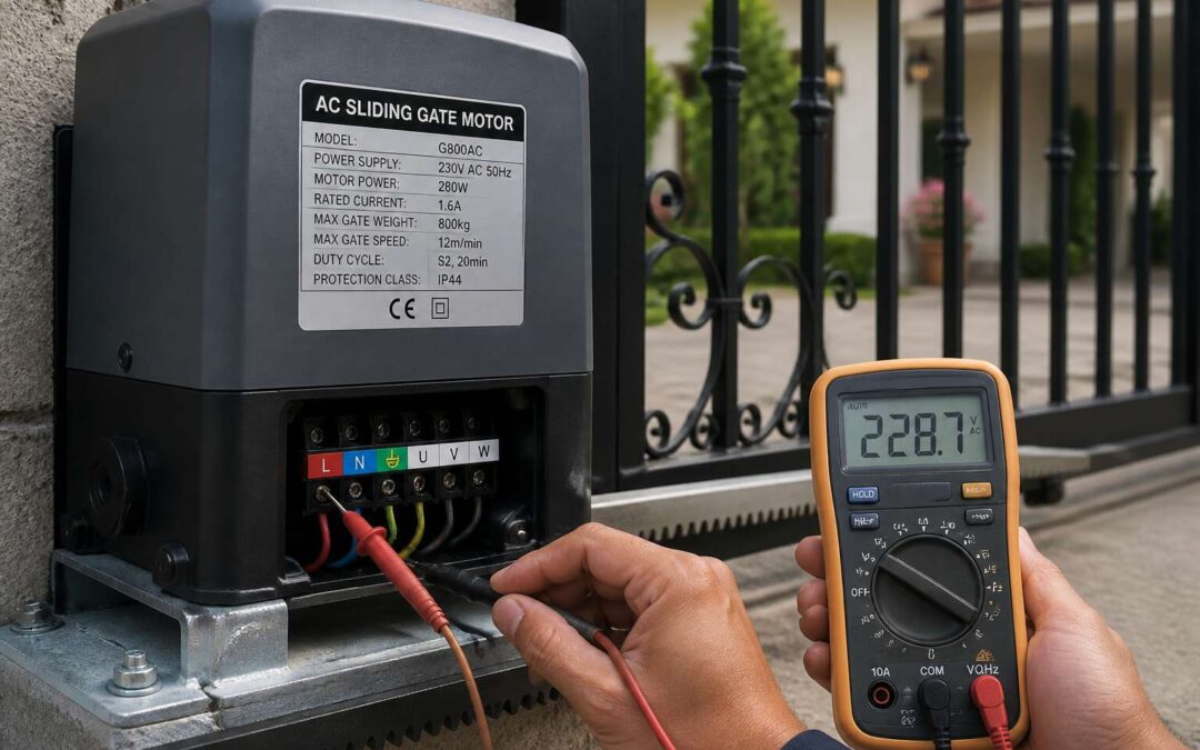
Key Electrical Terms for Gate Operators
Breaking Down Voltage and Current in Plain Language
Voltage is the electrical pressure that moves electrons. Current is the number of electrons flowing past a point each second. For any gate operator, these two terms determine the real work capability. The electric gate motor wattage is simply voltage multiplied by current.
When you read a specification label, you might see 24V and 3A. That tells you the motor requires 24 volts of pressure and draws 3 amperes of flow. Multiply them, and you get 72 watts, the wattage under normal load.
Here is a plain language breakdown:
– Voltage: the push behind the electrons
– Current: the volume of electrons moving
– Resistance: how much the circuit fights that movement
Understanding these terms helps you compare motors and ensure your battery or power supply delivers enough. In South Africa, gate motors commonly use 24V systems, so a higher current draw directly increases the wattage consumed.
What Duty Cycle Means for Armature Power
Resistance and duty cycle are the terms that separate a robust gate motor from one that overheats. For a 24V system, resistance dictates how much current the armature draws under load. The electric gate motor wattage, measured in watts, therefore shifts depending on mechanical resistance.
Duty cycle tells you how long that motor can sustain that draw without overheating. It is expressed as a percentage, for example 40%, which means four minutes of running followed by six minutes of rest. An underspecified duty cycle forces the electric gate motor wattage to climb beyond the wiring’s capacity.
Key terms to remember:
– Armature: the rotating component that converts electrical energy into mechanical motion
– Duty cycle: the ratio of powered operation to cooling downtime
– Service factor: the safety margin built into the motor’s continuous rating
Understanding Running vs. Start-up Power Draw
When you press the remote, the gate motor doesn’t gently ramp up. It demands a sudden surge! This start-up power draw can spike three to five times above the steady running draw, and that difference matters for your electric gate motor wattage calculations.
Here are two key terms that describe this behavior:
- Inrush current: the initial burst of electricity that overcomes static friction.
- Running current: the lower, sustained draw once the gate is moving.
Choosing an inverter based only on running current invites failure. I always tell clients to check the start-up surge first, because it often determines whether your system copes during load-shedding.
The Difference Between Rated Output and Actual Demand
Rated output is the number printed on the motor’s nameplate. It represents the maximum continuous power the motor can produce under ideal conditions. Actual demand is what the motor truly draws when the gate is heavy, the hinges are stiff, or the wind pushes against the panels.
These two numbers rarely match. A motor rated at 500 W may demand 700 W on a cold morning. That gap is why electric gate motor wattage must be calculated with real-world factors, not catalogue figures. The nameplate states a limit, not a forecast.
- Gate mass and balance
- Hinge and track friction
- Wind load and surface area
- Temperature and lubrication state
Each factor adds resistance. The motor’s rated output only tells you what it can sustain, not what your gate will ask of it. For accurate electric gate motor wattage, always compare actual demand against the inverter or supply capacity.
Factors That Influence Energy Draw in a Residential Drive System
Gate Weight, Length, and Sturdiness Impact
Consider the physical demands of your gate. A 300 kilogram steel gate needs far more torque than a lightweight aluminium alternative. That torque requirement translates directly into electric gate motor wattage. Longer gates amplify the problem. Every extra metre of length increases the moment arm, forcing the motor to work harder against inertia.
Sturdiness matters too. A rigid frame distributes force evenly. A flimsy one flexes under load, creating drag and misalignment. I see this failure mode constantly in the field. The result is higher current draw during every cycle. In South Africa, where security gates are often built from heavy steel tubing, electric gate motor wattage demands run higher than many homeowners expect.
Common culprits that inflate wattage:
– Poorly aligned hinges
– Excessive gate weight
– Long unsupported spans
Each factor pushes the motor closer to its duty cycle limit.
Sliding vs. Pivoting Mechanisms and Their Power Profiles
A sliding gate keeps its motor at constant load for the entire run. Wheels roll over each track segment, bearings add steady drag, and the large flat panel catches wind the whole way. The current draw stays high from first movement until the motor switches off. Any sand or grit in the track multiplies that combined strain, which is a familiar problem in South Africa’s dusty conditions. The flow is sustained, and this drive system needs a motor that handles fatigue across a full cycle, not just a moment of effort.
A pivoting mechanism behaves completely differently. It needs a sharp burst of torque to break the initial inertia of the leaf, but after that, the current demand drops dramatically once the swing continues. The peak is over in a brief moment, and the average wattage stays low. Sliding means constant resistance, while pivoting means one solid kick and then it merely keeps moving.
So the electric gate motor wattage rating that suits your installation depends on whether your gate drags or swings. The mass alone is not the deciding factor; the path’s movement changes the running draw dramatically.
Seasonal Disruptions: Cold Weather Fluid Dynamics
In the Highveld winter, morning temperatures drop below freezing. Those cold starts change the physics of your entire gate assembly. Grease thickens, rubber hardens, and metal contracts. Each factor raises the mechanical resistance your motor must overcome.
Lubricant viscosity at 2°C versus 20°C differs dramatically. Cold grease thickens on every bearing and gear, increasing resistance. The elevated resistance draws more current, directly impacting the electric gate motor wattage your system demands at dawn. You are fighting the physical state of every moving part.
Consider what stiffens in winter:
- Roller bearing grease becomes viscous and sluggish
- Rubber guide wheels lose elasticity
- Track steel contracts, narrowing tolerances
- Gearbox oil resists movement until warmed
Each frozen component adds a measurable layer of drag. A system that draws little power in summer can demand more during crisp morning runs. Understanding this seasonal variation helps you interpret why your electric gate motor wattage readings fluctuate throughout the year.
Layout of the Bound vs. Effective Path
The journey of a gate across its tracks is rarely the straight line it appears to be. What architects call the bound path, the literal steel and concrete route, is only half the story. The effective path is the true distance the electric gate motor wattage must overcome, a route defined by friction, drift, and the daily wear of the components themselves.
Ask any installer about a gate that sways when it moves, and they will tell you about the hidden drag. Over time, the bottom guide rollers create a groove in the track. The gate’s frame, even slightly twisted by the sun across the Johannesburg seasons, forces those wheels to scrub sideways. Each rub is a tiny resistance, an invisible hand holding the gate back. This mechanical inefficiency spikes the demand on the motor, drawing more current to sustain a speed that looks effortless to the observer.
Consider the subtle pressures that reshape the path:
– Uneven concrete slabs that cause the gate to tilt and bind on its rollers
– The constant pull of gravity on a gate that has settled unevenly into its foundation
– Wind loading that presses against the full surface of the gate, adding lateral pressure
– The misalignment of the rack and pinion, where teeth grind instead of glide
These factors are not static from a wattage perspective. A gate that runs smoothly when newly installed will develop a personality over time. The binding increases, the groves deepen, and the motor must work harder. The effective power required then drifts upward, far above the theoretical rating printed on the motor housing.
It is this divergence between the blueprint and the reality that creates the true cost. The electric gate motor wattage you calculate on paper rarely matches the figure on your meter during a late afternoon thunderstorm, when the air pressure drops and the gate’s mass feels heavier. The path is never fixed, it is a living thing, and the motor must negotiate every whim of its environment.
Breakaway-Mode Amplification
When a residential gate stands still, its motor rests. But the moment it must move, a hidden surge awakens. This breakaway-mode amplification demands a peak current that can dwarf the steady-state draw. The electric gate motor wattage stamped on the housing rarely reveals this transient spike, which can last only milliseconds yet dictate the entire system’s longevity.
Consider the static friction of a heavy leaf resting on a worn track. The motor must shatter that inertia. Without sufficient headroom in the wattage calculation, the unit will stall or overheat. Several elements amplify this breakaway demand:
- The settling of the gate overnight, increasing stiction.
- A slight warp in the frame due to thermal drift.
- The presence of a mechanical lock or latch.
Therefore, a prudent homeowner will assess the peak surge, rather than relying solely on the cruising wattage. The electric gate motor wattage must accommodate these brief, powerful episodes. Otherwise, the hidden drag will transform a graceful motion into a labored, costly struggle.
How Safety Extras and Add-Ons Modify Peak Demand
Electric gate motor wattage defines the electrical power consumption during operation, a critical specification for both performance and energy efficiency. Homeowners and installers often overlook this metric, focusing instead on pulling force or speed. However, understanding the wattage requirements ensures proper solar panel sizing, battery backup capacity, and protection against electrical circuit overloads. A standard residential electric gate motor wattage typically falls between 250 and 500 watts during active movement. This figure does not represent the constant draw, as the unit only consumes that peak amount while the gate is physically in motion.
The sliding gate motor wattage depends heavily on the physical characteristics of the gate itself. A lightweight aluminium gate with a length of four metres requires significantly less power than a solid steel gate of identical dimensions. Mass directly influences the required torque, and higher torque demands translate to higher electrical consumption. For example, a 500 kilogram sliding gate might require a motor with a nominal wattage of 400 to 600 watts to ensure reliable opening. Conversely, a 200 kilogram gate could operate effectively with a motor rated at 250 watts. The manufacturer provides a duty cycle rating alongside the electric gate motor wattage, indicating the recommended frequency of operation without overheating.
The duty cycle expresses the percentage of time the motor can run within a ten minute window. Most residential motors operate at a 25 percent duty cycle, meaning two and a half minutes of total running time. This scenario rarely poses a problem for a standard driveway. A commercial application with continuous traffic in a gated community requires a higher duty cycle, often 50 percent or more. A motor with insufficient wattage for the application will struggle, causing the thermal overload protection to activate. This safety feature interrupts the power supply to prevent damage to the windings, leaving the gate stuck in a partially open position until the motor cools down. Checking the electric gate motor wattage against the gate’s weight is the first diagnostic step for common performance failures.
The gate type also plays a role in determining the necessary wattage. A swing gate motor operates differently from a sliding unit. Swing gates require high torque at the start of the movement to overcome the initial inertia, especially if the hinges have increased friction. This initial surge can draw a current that is several times higher than the running current. The electric gate motor wattage listed on the product data sheet is the nominal power, but the startup surge can reach 1.5 times that value. An inverter or battery system sized purely on the nominal wattage will fail to provide enough current for the startup demand. For instance, a 300 watt swing motor might require a 500 watt inverter to handle the momentary peak. Any solar power solution needs a continuous power rating above the startup surge value, not just the average running figure.
The speed of operation also correlates with energy consumption. A motor that completes a full cycle in fifteen seconds uses more energy than a motor that takes twenty five seconds for the same movement. The faster acceleration requires a higher immediate forces, which in turn increases the peak current draw. While the total energy for one complete cycle might be similar due to the shorter run duration, the instantaneous electric gate motor wattage spikes higher. This factor is crucial even for gate automation using a simple battery backup unit. The backup battery must supply the peak current without experiencing voltage sag. A voltage drop below the motor’s rated threshold causes sluggish performance and can damage the controller board.
The standby power consumption is a separate figure from the operating wattage. The control board, transceiver for remote signals, and status indicators consume electricity continuously. In modern motors, this standby drain is minimal, usually in the range of 5 to 15 watts. While seemingly small, this constant load is the primary consumer of energy over a 24 hour period. A gate that operates only twenty times per day might use 300 watt hours for movement, but the standby electronics could consume over 200 watt hours. For solar installations, verifying the electric gate motor wattage for running and the separate standby draw is essential. The total daily energy is the sum of these two values.
Weather conditions introduce another variable affecting peak demand. Mechanical friction increases when temperatures drop below freezing, as grease thickens and rubber seals stiffen. Wind pressure on a solid panel gate adds significant load during operation. The electric gate motor wattage specification often assumes ideal conditions, so selecting a motor with a modest safety margin is wise. Choosing a motor with 20 percent more wattage than the calculated requirement provides a buffer for these environmental factors. The correct measurement focuses on the motor efficiency, not just the raw input power. A smaller motor running at its maximum capacity will have higher losses and generate more heat than a larger motor working comfortably within its range. The larger unit will consume more power on paper, but it will operate more reliably and require less maintenance.
Steps for Calculating Your Required Power Output
How to Locate the Manufacturer’s Peak Spec
The motor hides its hunger. To find the true electric gate motor wattage, you must calculate the required output, not rely on guesswork. I measure the gate’s mass, the track’s resistance, and the expected wind load. Then I apply a safety factor. This yields the continuous demand your system needs.
Locating the manufacturer’s peak spec requires a different ritual. Follow these steps:
- Read the nameplate for the locked rotor amperage.
- Find the datasheet’s starting wattage, not the running figure.
- Cross-reference the surge duration with your inverter’s capacity.
The peak spec reveals the moment of ignition. Calculating required output involves torque, distance, and time. Divide the work by seconds, then multiply by a margin. In South Africa, load shedding exposes any miscalculation. The nameplate wattage is a promise; the peak spec is the reality. Both numbers matter for sizing your backup power.
Working Through a Worked Example of Power Math
Load shedding punishes guesswork. The electric gate motor wattage you calculate must match real conditions, not the brochure. I start with a sequence that forces precision.
- Weigh the gate and measure the track resistance.
- Multiply the mass by the friction coefficient and gravity to get the required force.
- Multiply that force by your desired opening speed to obtain continuous power.
- Apply a safety factor of 1.5 to account for wind load and worn rollers.
Now a worked example. A 200 kg gate with a friction coefficient of 0.15 needs 294 N of force. At 0.3 m/s, that equals 88 W. Apply the safety factor and the continuous electric gate motor wattage is 132 W. That is the number to compare against inverter ratings. The start-up surge will always exceed this figure, so your backup needs headroom beyond the calculated value.
Adjusting the Calculation for Unexpected Main Power Swells
When the lights flicker in a South African suburb, the first question is usually about the gate. A gate stuck open or closed during load shedding creates a security risk and a logistical headache. The solution starts with understanding your electric gate motor wattage. This number tells you what your inverter, battery, or backup system truly needs to handle.
Calculating the required power output begins with a simple physical formula. The force needed to move a gate equals its mass multiplied by the friction coefficient of the rollers and track. Take a common residential example: a 200 kg steel gate with a friction coefficient of 0.15. That gives you 294 Newtons of force. Multiply that by the desired opening speed, say 0.3 meters per second, and you get 88 Watts of continuous mechanical power.
– Determine the gate mass in kilograms.
– Multiply by the friction coefficient (typically 0.1 to 0.2 for well-maintained rollers).
– Convert the result to Newtons.
– Multiply by your preferred linear speed in meters per second.
– The answer is your base wattage.
Now add the safety factor. Wind loads, worn bearings, and slight misalignment all increase resistance. Multiply your base figure by 1.5. In the example above, 88 Watts becomes 132 Watts. This is the continuous electric gate motor wattage you should compare against motor specifications and inverter ratings.
Unexpected main power swells complicate the picture. South Africa’s grid regularly experiences voltage spikes or dips, especially during localised faults or when supply is restored after load shedding. A motor rated for 132 Watts continuous can draw three times that amount during startup, and a voltage swell can push the current even higher. Your inverter must tolerate that momentary surge without tripping. Look for a unit with a peak rating at least 200% of the continuous value. Add a surge arrestor at the gate motor’s supply point to protect sensitive electronics. One more adjustment: if your gate is heavier than 200 kg or your driveway slopes, recalculate from scratch. The formula is the same, but the numbers change the outcome. Knowing your exact figure prevents the frustration of an undersized backup system failing at the worst possible moment.
Selecting Transformers or Pulse Regulators to Match Estimates
Once you have a baseline electric gate motor wattage from the mechanical side, stop pretending your gate lives in a laboratory. Recalculate with the real world included. Add 50% for friction shifts, double for starting surge, and only then inspect the power supply. The difference between a robust system and a smoldering one is rarely the motor itself. It is the transformer or pulse regulator feeding it.
Selecting that component to match your estimates is where most backups fail. Owners match the running draw and ignore the inrush current. A pulse regulator absorbs the spike gracefully. A transformer, however, must be sized at 1.5 times your total calculated demand.
Work through it like this:
- Take your continuous electric gate motor wattage and add a 100% reserve for startup.
- Divide that figure by your supply voltage to get the required amperage.
- Match that amperage to a regulator or transformer with a higher pulse rating.
Commit these numbers to paper before purchasing anything. Your gate will open when it should and stay closed when it must.
Comparing Operator Classes Based on Supply Needs
Light-Duty Automotive Drive vs. Industrial-Supply Systems
Two operators can both claim to open a 4-metre gate, yet their electric gate motor wattage can differ by a factor of ten. Most residential units use automotive starter motors that draw from a 12V or 24V battery. Industrial-supply systems, by contrast, run off three-phase AC mains and hold a steadier current profile.
The difference shows up in how each system handles load. A light-duty drive may surge to 30 amps during breakaway, whereas an industrial unit might hold a lower but continuous draw. I’ve seen that alone change transformer sizing and cable thickness.
Supply requirements diverge at the distribution board:
- Light-duty motors typically need a dedicated rectifier and battery bank.
- Industrial units require a phase-balance check before installation.
Each class demands its own approach to peak demand, and the electric gate motor wattage for one will not translate across categories.
Efficiency in Slow Motion vs. Fast Slewing
A nameplate that reads 500 watts will behave differently depending on how fast the armature slews. Slow-moving operators crawl into position, holding a steady, modest current that a simple rectifier can regulate. Fast-slewing units reach full speed in a blink, forcing the drive to pull a heavy surge that distorts the mains supply. Both may share the same electric gate motor wattage, but the demand each places on the grid is fundamentally different.
These two classes rarely present the same face to the distribution board:
- The slow class tolerates a sagging main feed without losing torque.
- The fast class needs a stiff supply, otherwise the acceleration slows and the controller errors.
That difference is why a nameplate rating means little until you know how quickly the operator applies it.
Less Input for More Output: Selecting the Right Params
When you size an operator against a shared supply, the key insight becomes acute. A machine with a modest electric gate motor wattage can outperform a larger unit if its drive parameters accept the soft main. Less input, more output guides the selection.
Selecting the right params means setting the soft-start and the current curve to match the local transformer. That calibration allows a smaller motor to deliver the required breakaway force without draining the feeder.
- Adjust the voltage sag tolerance
- Set the acceleration curve for the drop
- Use a sinusoidal filter to reduce the surge
Hybrid Battery Ready Types and Back-Feed RMS
“Load shedding has a way of exposing hidden truths about your gate operator: roughly 40% of standby failures trace back to an undersized buffer supply, not the motor itself.”
Comparing operator classes by supply needs shifts the spotlight from raw power to resilience. A single-phase AC induction unit, for instance, demands a steady 230V baseline and struggles when the grid dips below 200V. A DC brushless counterpart, on the other hand, thrives on a nominal 24V bank, pulling only what the battery can safely discharge. The electric gate motor wattage stamped on the box rarely tells you which class tolerates a sagging municipal feed better. You need to match the operator’s internal topology to your actual supply profile, not just the brochure’s peak figure.
Hybrid battery ready types occupy a middle ground. These units trickle charge a float bank from the mains during quiet hours, then draw during operation. That design smooths the demand curve, so the motor never spikes the feeder. But the battery adds its own consumption, a constant parasitic load that nudges the effective electric gate motor wattage higher than the nameplate suggests. Account for that standby draw when you calculate the transformer size.
Back-feed RMS is the measure most installers ignore. When your gate runs downhill, the motor becomes a generator, shoving energy back into the supply line. A cheap linear operator might send a dirty waveform upstream, tripping sensitive protection relays. A quality unit with a sinusoidal back-feed filter keeps that return current clean. In areas with heavy phase imbalance, a higher RMS tolerance on the back-feed path lets a smaller motor handle a steeper driveway without overheating. The rated electric gate motor wattage stays the same, but the effective stamina improves markedly.
Practical Ways to Shrink Consumption Without Halting Performance
Adding Gear Gains to Lower Armature Load
Most homeowners assume that a heavier gate demands a heavier motor, but the real culprit is often the load applied to the armature before it even turns. What many miss is that the gearbox ratio determines how hard the motor has to work to overcome inertia. The right gearing transforms a struggling motor into one that coasts through its cycle with ease, which directly reduces the electric gate motor wattage drawn from your supply.
Gear reduction is essentially a mechanical advantage. When you increase the gear ratio, you multiply torque at the output shaft, but you reduce the speed at which the gate moves. This slower, deliberate motion allows the motor to spin faster internally while the gate itself moves at a safe pace. The result is a lower current draw during the run phase. Here is how it pays off:
– Lower armature heat buildup, which preserves insulation over time.
– Reduced peak demand during the acceleration phase.
– A smoother start that lessens wear on the rack and pinion teeth.
A common error is selecting a gate operator with a gearbox designed for a lighter leaf, then relying on the motor’s raw power to compensate. That approach spikes the electric gate motor wattage far beyond what the nameplate suggests. Instead, a larger motor running at a higher RPM with a substantial gear reduction will move the same gate with less electrical input because the mechanical work is shifted from electrical force to mechanical advantage.
Of course, adding gear gains is not a universal fix. The sliding resistance of your specific tracks and rollers still determines the baseline load. But once that baseline is addressed, the gearing becomes the lever you can pull to optimise consumption. For installations with long travel distances, this translates into meaningful savings over hundreds of cycles, not just a marginal theoretical improvement. The trick is matching the reduction ratio to the gate’s mass, not to the maximum speed you desire.
Green Add-Ons Using Photocell Schedules
Reducing electric gate motor wattage does not require sacrificing speed or reliability. Start by confirming the motor operates within its rated duty cycle. An oversized motor wastes energy on every cycle. A correctly sized motor draws less current while still handling the gate’s mass. Check the limit switches for proper adjustment. Misaligned switches cause unnecessary run time and higher wattage draw.
Photocell schedules offer a practical green add-on. A photocell can disable the gate motor during daylight hours when access is less frequent. This shrinks standby losses and reduces total consumption. For example, set the photocell to allow operation only between 6 PM and 6 AM. The motor rests for twelve hours. That cuts energy use without affecting typical usage patterns.
Consider these low cost adjustments:
– Reduce opening speed on residential gates. Slower movement uses less torque and lowers peak wattage.
– Install a soft start controller. It ramps up current gradually, avoiding the surge that spikes demand.
– Use a timer to turn off the motor’s standby power when not in use.
Each change trims electric gate motor wattage while maintaining full functionality. The key is matching run time to actual need, not leaving the motor on a constant cycle. Photocell timing works best for gates used mainly at night, such as community entrances. For day time access, a motion sensor paired with a delay switch offers similar savings. These methods keep the motor responsive while lowering every kilowatt hour consumed.
Zero-Standby Smart Transforms
Standby power is the silent thief of efficiency. Many gate motors draw a constant trickle of current, even when the gate has not moved for hours. That is pure waste. The zero-standby transformer is the modern answer. It cuts the electrical link completely when the motor is idle. The gate stays ready, but the meter stops spinning. This does not compromise the closing speed or the safety of the system. It is a simple change of components that pays for itself over time.
The smart controller takes this further. It learns the daily rhythm of the gate. If the gate does not open at midday, the controller reduces the internal voltage. This shrinks the heat loss inside the motor housing. Lower heat means less resistance, which drops the electric gate motor wattage draw during peak loads. This type of adaptive logic is especially useful in South Africa, where load-shedding schedules force irregular usage patterns. The system becomes proactive, not reactive.
Energy Metrics and Logging Features
A 30% reduction in running costs is realistic when you shift from reactive maintenance to proactive energy management. The first practical step is voltage optimisation. Many installations run on a higher supply voltage than the motor actually requires, which forces the armature to draw excess current. A simple buck-boost transformer or a variable frequency drive can trim that input to the precise operating range, reducing heat and cutting the electric gate motor wattage during every movement cycle.
Another effective approach is demand scheduling. Pair the motor controller with a timer that aligns high-consumption tasks with off-peak tariff windows, if your property runs on a time-of-use meter. For example, programme the gate to perform its self-test lubrication cycle at 2 AM, when electricity is cheaper and the grid is under less pressure. This shifts the load without altering performance during business hours.
– Log daily starts, run time, and peak amp draws.
– Track cumulative kilowatt-hours per month.
– Flag any recurring error codes that indicate mechanical drag.
– Record voltage sag events during local load-shedding.
These metrics reveal patterns. If the electric gate motor wattage spikes every Monday morning, you might have a build-up of dust on the track after weekend inactivity. Logging turns guesswork into a targeted maintenance plan. It also provides the data needed to justify a solar or battery upgrade, since you can prove the exact consumption profile. The meter does not lie, and neither does the gate.