Understanding Gemini Gate Motors
Overview of Gemini Gate Motors
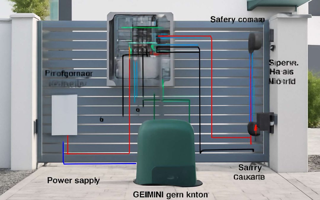
Gemini gate motors have revolutionized the way we think about home security and convenience. They blend reliable technology with user-friendly features, making them a popular choice across South Africa’s diverse landscape. Understanding the intricacies of the gemini gate motor wiring diagram is essential for both professional installers and DIY enthusiasts aiming for seamless operation. This wiring diagram provides a blueprint that ensures safe and efficient power distribution, preventing costly errors and ensuring longevity of the motor.
At its core, a Gemini gate motor wiring diagram is a detailed schematic that illustrates how each component connects—power supply, control boards, remote receivers, and safety sensors. Grasping this wiring layout helps in troubleshooting potential issues and customizing setups to suit specific gate configurations. For those venturing into gate automation, recognizing the logic behind the wiring not only enhances safety but also optimizes performance, ensuring your gate functions flawlessly under South Africa’s unique conditions.
Key Features and Benefits
Gemini gate motors are the unsung heroes of modern home automation—delivering both security and convenience with a touch of sophistication. Their key features include robust build quality, quiet operation, and seamless integration with remote controls and safety sensors. But what truly sets them apart is how cleverly their wiring system is designed to maximize efficiency and longevity.
Understanding the gemini gate motor wiring diagram is like having a backstage pass to the motor’s inner workings. It reveals the precise connections between the power supply, control boards, and safety sensors—ensuring every component plays nicely together. This knowledge isn’t just for the tech-savvy; it’s a vital tool for troubleshooting and customizing your gate setup. Plus, a well-versed understanding of the wiring diagram helps prevent those costly errors that can turn a smooth installation into a frustrating ordeal.
In essence, a comprehensive gemini gate motor wiring diagram acts as the blueprint for reliable operation. Whether you’re a seasoned installer or a DIY enthusiast in South Africa, mastering this diagram empowers you to optimize performance while maintaining safety standards. After all, a well-wired gate motor isn’t just about opening and closing—it’s about peace of mind, long-term durability, and effortless access. And yes, that all begins with understanding the wiring diagram—because a gate that’s wired right is a gate that works right.
Common Models and Specifications
Understanding the different models of Gemini gate motors is crucial for anyone diving into the world of home automation in South Africa. Each model offers unique specifications tailored to varying security needs and gate sizes. Whether it’s the compact yet powerful Gemini 2000 or the heavy-duty Gemini 4000, their core components and wiring configurations differ slightly but follow a consistent logic. This consistency simplifies the process of mastering the gemini gate motor wiring diagram, even for beginners.
For instance, most Gemini gate motors feature dual control boards and safety sensor inputs, which are vital for reliable operation. Recognizing these commonalities helps in troubleshooting and customizing installations. Here’s a quick overview of key specifications to keep in mind:
- Motor power ratings
- Control terminal configurations
- Sensor input types and wiring requirements
By familiarizing yourself with these specifications, you can confidently interpret the gemini gate motor wiring diagram and ensure your setup is both efficient and durable. Whether installing a new system or maintaining an existing one, understanding these models guarantees smooth, secure access every time.
Essential Components of the Wiring Diagram
Power Supply Requirements
Power supply requirements form the backbone of any reliable gemini gate motor wiring diagram. Without a consistent and correctly rated power source, even the most sophisticated gate automation systems are destined to falter. The essence of a seamless operation lies in understanding the delicate balance between voltage stability and current capacity—an often overlooked facet that can make or break your installation’s longevity.
At its core, the wiring diagram for a gemini gate motor demands a dedicated power circuit that can handle the motor’s peak load. This isn’t merely about plugging in; it’s about ensuring that the wiring and circuit breaker are appropriately rated to prevent overheating or electrical failure. For South African installations, where power fluctuations are common, integrating surge protection and voltage stabilizers becomes an act of foresight and prudence.
- The motor’s voltage rating
- The current draw during peak operation
- The necessity for protective devices such as fuses or circuit breakers
- The grounding requirements to ensure safety and proper functioning
Each element in the power supply chain must be meticulously chosen to match the specifications laid out in the gemini gate motor wiring diagram. Only then can the system operate with both efficiency and safety—an unspoken moral obligation in safeguarding property and lives alike. As you delve into wiring your gate, remember: precision and understanding are your most potent tools in this quiet, yet profound, act of engineering.
Control Panels and Keypads
Within the shadowed corridors of a well-crafted gemini gate motor wiring diagram, the control panels and keypads serve as the nervous system—silent yet vital. These components transform a simple command into a symphony of mechanized motion, commanding the gate with an almost hypnotic grace. The control panel, often concealed within a dark cabinet, houses the intricate circuitry that ensures each pulse and signal is perfectly synchronized.
Keypads, the interface between human intent and mechanical destiny, must be wired with precision. Their placement is no mere matter of convenience but a strategic decision—an entry point into the guarded domain of your property. When wiring these elements, attention to detail is paramount; they require stable connections, protected from the harsh South African elements that threaten to disrupt their delicate balance.
In the gemini gate motor wiring diagram, control panels often incorporate:
- Relays and contactors that manage the motor’s power flow
- Emergency stop buttons—guardians of safety in a darkened world
- Connection terminals that must be meticulously secured to prevent rogue voltages
Meanwhile, the keypads must be linked to the control panel with shielded cables, ensuring that each command is delivered without distortion or interference. The orchestration of these components transforms the mundane wiring task into a ritual—one that demands both reverence and meticulous craftsmanship. In this dance of shadows and light, every connection whispers promises of security, efficiency, and silent guardianship of what lies beyond the gate.
Limit Switches and Safety Devices
Within the intricate web of a gemini gate motor wiring diagram, limit switches and safety devices form the silent guardians—integral to ensuring both operational precision and security. These components serve as the moral compass, guiding the gate’s motion and preventing catastrophic mishaps. Limit switches act as the gatekeeper’s conscience, signaling when the gate has fully opened or closed, thus avoiding mechanical strain or damage. They are often wired into the control circuit, ensuring the motor ceases operation at precisely the right moment.
Safety devices are not mere add-ons; they are the moral backbone of the entire system. Emergency stop buttons, photoelectric sensors, and safety edges create a layered defense, protecting both users and property. When correctly integrated into the gemini gate motor wiring diagram, these components elevate the system from mere automation to a vigilant sentinel.
- Limit switches to define operational boundaries
- Photoelectric sensors to detect obstructions
- Emergency stop buttons for immediate shutdown
Understanding the placement and wiring of these essential components is crucial. Their proper integration ensures the gate not only functions seamlessly but also embodies safety and reliability—fundamental pillars in the realm of gate automation in South Africa’s often unpredictable environment. In this meticulous dance of connections, every wire carries the weight of assurance, every switch a testament to responsible design.
Remote Controls and RF Receivers
Remote controls and RF receivers form the heartbeat of a reliable gate automation system. They offer convenience, but their importance extends beyond simple operation—security and seamless access depend on their proper wiring. In the context of the gemini gate motor wiring diagram, understanding how these components interact is crucial for both safety and efficiency.
Typically, the remote control transmits signals to the RF receiver, which then activates the motor. The receiver is wired into the control circuit, bridging the gap between user commands and automated action. To ensure optimal performance, it’s essential to follow the wiring diagram meticulously, especially regarding power supply and signal connections.
- Connect the RF receiver to the control panel following the manufacturer’s specifications.
- Link the remote control to the receiver, ensuring frequency compatibility for reliable operation.
- Wire the receiver output to the gate motor control terminals, facilitating smooth command execution.
By adhering to these wiring principles, you guarantee that the remote control system remains responsive and secure. In South Africa’s unpredictable environment, a well-wired gemini gate motor wiring diagram isn’t just about convenience—it’s about safeguarding assets and ensuring peace of mind. Proper integration of remote controls and RF receivers transforms a basic automation setup into a resilient, user-friendly system ready for any challenge.
Step-by-Step Guide to Gemini Gate Motor Wiring
Preparing the Installation Site
Preparing to wire your Gemini gate motor is like embarking on a quest—precision and patience are your greatest allies. Before diving into the intricate world of electrical connections, ensure your installation site is perfectly primed. Clear the area of any debris, ensure stable grounding, and double-check your power supply. A well-prepared site not only guarantees safety but also paves the way for a seamless wiring process.
Next, gather all necessary tools and materials, including the Gemini gate motor wiring diagram, which acts as your map through this adventure. Familiarize yourself with the diagram, noting the key connection points like power input, control terminals, and safety switches. To simplify your journey, follow this step-by-step sequence:
- Turn off the main power supply to avoid any mishaps.
- Connect the motor’s power terminals to the main supply, ensuring correct polarity.
- Wire the control panel to the motor, referencing the Gemini gate motor wiring diagram for precise terminal locations.
- Install limit switches and safety devices, making sure they are correctly aligned with the wiring diagram for optimal operation.
Remember, meticulous attention to detail and adherence to the Gemini gate motor wiring diagram will unlock a smooth, reliable gate operation—transforming your driveway into a portal of effortless access and security.
Gathering Necessary Tools and Materials
Wiring your Gemini gate motor isn’t just a task—it’s an art form that demands precision and deliberate focus. Before the sparks fly, gather all the essential tools and materials to ensure a smooth installation. A well-stocked toolkit transforms a daunting task into an achievable feat. You’ll need wire strippers, screwdrivers, a voltage tester, and perhaps crimping tools, all laid out and ready to go.
To keep the process organized, create a checklist of key components such as the power supply, control panel, limit switches, and safety devices. The Gemini gate motor wiring diagram becomes your blueprint—guiding your every connection with clarity. With everything in place, follow this sequence:
- Turn off the main power supply to prevent any mishaps.
- Identify the motor’s power terminals, then connect them to the main power, ensuring correct polarity—this is crucial for safe operation.
- Wire the control panel to the motor, referencing the Gemini gate motor wiring diagram for precise terminal locations.
- Install limit switches and safety devices, aligning them meticulously according to the wiring diagram to enhance safety and functionality.
Every connection should be double-checked against the Gemini gate motor wiring diagram. Missing a step or miswiring can lead to operational issues or safety hazards. Patience and attention to detail are your best allies in this journey—because flawless wiring unlocks a reliable, secure driveway automation that feels almost supernatural in its seamless operation!
Wiring the Power Supply
Wiring the power supply for your Gemini gate motor is a pivotal step that underscores the importance of precision in automation systems. A stable and correctly wired power source not only ensures reliable operation but also safeguards against potential hazards. As you begin this process, always remember that the Gemini gate motor wiring diagram is your most trusted blueprint, guiding every connection with meticulous detail.
Start by turning off the main power supply—safety first, always. Next, identify the motor’s power terminals, which are clearly marked on your Gemini gate motor wiring diagram. Connecting these terminals to your power source requires careful attention to polarity; incorrect wiring here can cause operational issues or damage the motor. To streamline the process, consider this simple outline:
- Ensure the power supply matches the voltage requirements specified for your model.
- Use appropriate gauge wire to handle the current load safely.
- Connect the live (hot) wire to the designated terminal, following the Gemini gate motor wiring diagram.
- Attach the neutral wire securely, maintaining proper connection standards.
- Finally, connect the earth or ground wire to the grounding terminal for safety.
Double-check every connection against the Gemini gate motor wiring diagram before restoring power. This careful approach guarantees not just a seamless installation but also long-term safety and durability. Every wire laid with intention is a step toward a driveway automation system that operates as smoothly as a well-rehearsed symphony—reliable, efficient, and almost intuitive in its function.
Connecting the Control Panel
Wiring a Gemini gate motor control panel is an exercise in precision, a delicate dance that transforms raw components into a symphony of automation. While the process might seem formidable at first glance, a well-understood Gemini gate motor wiring diagram acts as a guiding star—illuminating each step with clarity and purpose. Connecting the control panel involves more than just physical wiring; it’s about forging a reliable communication pathway that ensures seamless operation and long-term durability.
Begin by carefully identifying the terminal points on your control panel, referencing the Gemini gate motor wiring diagram for exact placement. Typically, the control panel features dedicated inputs for remote controls, safety sensors, and limit switches. To streamline the process, follow this simple sequence:
- Turn off the main power supply—never underestimate the importance of safety!
- Connect the control panel’s power input to your main power source, ensuring correct polarity and voltage compatibility.
- Wire the limit switches to their designated terminals. These devices are pivotal in preventing over-travel, safeguarding both the gate and users.
- Attach the remote control receiver to the relevant control terminals, enabling wireless operation with ease.
- Securely connect safety devices such as photoelectric sensors, adhering to the specifications outlined in your Gemini gate motor wiring diagram.
Every connection should be double-checked against the wiring diagram, a step that’s often underestimated but crucial for flawless operation. When all connections are verified, restoring power transforms your carefully laid wiring into a conduit of effortless automation, ready to perform reliably even in the most demanding environments. The intricate artistry of wiring a Gemini gate motor control panel becomes less daunting when approached with patience and an unwavering commitment to detail.
Integrating Limit Switches
Wiring a Gemini gate motor with integrated limit switches might seem like deciphering an ancient manuscript, but with a reliable Gemini gate motor wiring diagram in hand, it’s more akin to following a treasure map—less mystery, more clarity. The secret lies in understanding how to seamlessly integrate limit switches, those unsung heroes that prevent your gate from turning into a runaway train. These devices act as the gate’s safety net, halting motion before it oversteps its boundaries, ensuring both longevity and safety.
Start by locating the limit switch terminals on your Gemini gate motor. According to the wiring diagram, these are crucial connection points. Carefully connect the limit switches to their designated terminals, ensuring they are wired correctly to trigger stopping points. This step is vital: a miswired limit switch can cause the gate to behave like a rebellious teenager—unpredictable and potentially damaging.
Next, following the Gemini gate motor wiring diagram, connect the limit switches in parallel with the control circuit. This ensures that when the limit switch is activated, it sends a clear signal to halt the motor—no drama, just precision. For added security, consider using a multimeter to verify continuity and proper electrical flow before powering up the system.
Incorporating limit switches isn’t just about safety; it’s about creating a harmonious ballet of mechanical and electrical components. When all connections are made according to the Gemini gate motor wiring diagram, the result is a system that’s both robust and reliable—ready to handle the rigours of South African weather and the whims of your driveway.
Wiring Safety and Emergency Stops
Safety in wiring your Gemini gate motor is paramount. It’s a delicate dance of electrical precision that transforms a simple gate into a fortress of security. One crucial step in this process is understanding the wiring safety protocols, which include disconnecting the power supply before commencing any work. This ensures that accidental shocks or short circuits are avoided, safeguarding both the technician and the equipment. Additionally, incorporating emergency stops into your wiring setup creates a fail-safe mechanism—quickly halting the gate’s movement in urgent situations.
When wiring the Gemini gate motor, clarity is key. Using a comprehensive Gemini gate motor wiring diagram helps visualize each connection, reducing the risk of errors. An effective method involves:
- Identifying the emergency stop terminals on the control panel
- Connecting the emergency stop button in series within the control circuit
- Testing the circuit with a multimeter to verify continuity before powering up
This approach not only enhances safety but also ensures the system’s reliability under South African weather conditions. Remember, meticulous attention to wiring safety and emergency stops transforms your installation from a potential hazard into a seamless, secure operation—making every driveway a haven of peace and security.
Interpreting the Wiring Diagram
Reading Symbols and Labels
Interpreting the gemini gate motor wiring diagram can feel like deciphering an ancient script—until you understand its symbolism and labels. These diagrams aren’t just random squiggles; they’re a visual language that communicates how electricity flows through your gate motor system. Recognizing common symbols—such as switches, relays, and power sources—turns what once seemed cryptic into a straightforward map. Labels further clarify each connection, ensuring you don’t accidentally wire your gate to a disco ball or, worse, fry the entire system.
For those venturing into the world of gemini gate motor wiring diagram, a helpful tip is to familiarize yourself with the legend often provided. This legend is your Rosetta Stone, translating icons into real-world components. Additionally, paying close attention to the wiring labels helps prevent confusion, especially in complex installations where multiple control points are involved. Remember, understanding these symbols and labels isn’t just about safety; it’s about making your installation as smooth as a well-oiled gate. After all, a clear wiring diagram is the backbone of a reliable, long-lasting system.”
Identifying Key Connections
Interpreting the gemini gate motor wiring diagram is akin to unlocking a secret code — every line and symbol whispers a tale of electrical harmony. Once you recognize the key connections, the entire symphony of your automated gate begins to reveal itself. It’s not merely about tracing wires; it’s about understanding the language that ensures your gate’s swift, safe operation.
For clarity, focus on the core linkages—power sources, control units, and safety switches. These form the backbone of a dependable system. To simplify navigation, consider this ordered approach:
- Identify the main power supply connection.
- Locate control panel wiring points, ensuring they align with your remote control’s signals.
- Trace the limit switches, which act as the gate’s silent guardians, signaling when to stop or reverse.
By following this logical thread, deciphering the gemini gate motor wiring diagram transforms from an intimidating puzzle into an intuitive map. Recognizing the significance of each connection helps prevent costly mistakes and guarantees that your gate’s operation remains flawless—an elegant dance of mechanics and electricity. Truly, understanding these connections is like composing a masterpiece, where every note plays a vital role in harmony.
Troubleshooting Common Wiring Issues
Interpreting the wiring diagram of your Gemini gate motor can feel like unraveling a complex tapestry, especially when unexpected issues arise. Often, problems stem from simple wiring faults that go unnoticed—poor connections, loose wires, or incorrect terminals. These glitches can cause the gate to malfunction, delay, or even refuse to operate altogether.
Troubleshooting common wiring issues starts with a careful visual inspection. Look for any frayed cables, signs of corrosion, or loose fittings. If the wiring diagram of your Gemini gate motor isn’t followed precisely, the entire system’s harmony can break down. For instance, incorrect wiring of safety devices or limit switches can lead to unexpected gate stops or reversals.
To assist with this process, consider this step-by-step approach:
- Verify the main power supply connection, ensuring it’s secure and matches the Gemini gate motor wiring diagram.
- Check control panel wiring, confirming all signals align correctly with your remote controls and keypads.
- Inspect limit switches for proper placement and wiring, preventing the gate from over-traveling or closing prematurely.
Understanding these wiring nuances isn’t just about fixing problems—it’s about restoring confidence in your automated gate’s safety and reliability. Each connection plays a vital role in ensuring smooth, secure operation, especially in rural settings where dependable access control can mean everything.
Safety Tips and Best Practices
Ensuring Proper Grounding
In the realm of automated gateways, the importance of unwavering safety cannot be overstated. A well-implemented grounding system acts as the enchanted shield that safeguards both the equipment and those who operate it. Ensuring proper grounding is a vital step when working with the gemini gate motor wiring diagram, as it prevents electrical surges from turning a simple installation into a perilous ordeal. When grounding, always verify that your connection to a true earth ground is solid, stable, and compliant with local electrical standards.
To further fortify safety, consider integrating emergency stop mechanisms that are not only accessible but also clearly labeled. These safety devices serve as a safeguard during unforeseen malfunctions, providing peace of mind to users. Remember, safety and reliability are intertwined—wiring the gemini gate motor with meticulous care and adherence to best practices will ensure the longevity of your installation and the well-being of all who depend on it. Proper grounding, when combined with vigilant safety measures, transforms a technical task into a ritual of protection, echoing the ancient wisdom that safety is the true guardian of progress.
Avoiding Short Circuits
Safety should never be an afterthought when dealing with the gemini gate motor wiring diagram—think of it as the invisible armor that keeps everyone protected. Avoiding short circuits is paramount; a tiny mistake can turn your sleek installation into a fireworks display of sparks and smoke. Always double-check your wiring connections before powering up, because a loose wire is like a ticking time bomb waiting to malfunction.
To minimize risks, incorporate robust safety measures such as emergency stop mechanisms that are easily accessible and clearly labeled. These safety devices act as the guardian angels of your gate system, ready to intervene during unforeseen malfunctions. Remember, a well-wired gemini gate motor can be a fortress of reliability, but only if safety is woven into the wiring process from the outset. Proper planning and meticulous attention to detail turn what could be a hazardous task into a seamless, secure operation.
Testing the Wiring Before Operation
Before flipping the switch on your meticulously wired gemini gate motor, a thorough safety check is essential. Testing the wiring before operation isn’t just a step—it’s a safeguard against unforeseen malfunctions that could turn your installation into a hazardous scenario. Carefully inspecting each connection ensures that no loose wires or incorrect terminations remain hidden, reducing the risk of short circuits or electrical faults. Remember, even a single misplaced wire can cause a cascade of issues, compromising both safety and reliability.
To streamline this process, consider following a structured approach. Use a multimeter to verify continuity and correct voltage levels across key points in your gemini gate motor wiring diagram. This simple yet effective method acts as an early warning system, alerting you to potential problems before energizing the system. Incorporating safety devices like emergency stop buttons during testing further enhances protection, giving you peace of mind during initial power-up. Safety in wiring isn’t just a precaution—it’s the foundation of a dependable, long-lasting gate system.
Compliance with Electrical Safety Standards
Safety compliance is non-negotiable when working with a gemini gate motor wiring diagram. Electrical standards in South Africa emphasize thorough checks before energizing the system. Ensuring that every connection adheres to local regulations not only protects users but also guarantees long-term reliability. A single oversight can lead to costly repairs or dangerous malfunctions.
Implementing best practices involves using appropriate safety devices, such as emergency stop buttons, which should be tested regularly. When wiring your gemini gate motor, it’s crucial to follow a structured approach—checking each connection with a multimeter helps identify potential issues early. Remember, proper grounding and avoiding short circuits are fundamental steps that underpin safety and system integrity.
To maintain high standards, consider the following:
- Always wear insulated gloves and safety gear during installation.
- Use certified components that meet electrical safety standards.
- Adhere strictly to the gemini gate motor wiring diagram to prevent errors.
By respecting these safety tips and best practices, you ensure your gate system remains dependable, compliant, and safe for everyday use. Safety in wiring isn’t just a rule; it’s the foundation of a durable gate automation system that stands the test of time in South Africa’s diverse environments.
FAQs About Gemini Gate Motor Wiring
Can I wire my Gemini gate motor myself?
Wiring a Gemini gate motor might seem like a daunting task, but with the right guidance, it can transform into a manageable craft. Many homeowners wonder, “Can I wire my Gemini gate motor myself?” The answer depends on your familiarity with electrical systems and comfort level with safety protocols. While the gemini gate motor wiring diagram offers a detailed blueprint, understanding it thoroughly is essential before attempting any installation.
For those with a cautious spirit and a keen eye for detail, following the wiring diagram step-by-step can be rewarding. However, it’s important to remember that electrical work carries inherent risks, especially if you’re unfamiliar with local safety standards. If you choose to proceed independently, ensure you adhere strictly to the wiring diagram and safety guidelines. Alternatively, consulting a professional can ensure your gate motor operates seamlessly, safeguarding both your property and peace of mind.
What to do if the gate doesn’t operate correctly?
If your Gemini gate motor isn’t functioning as it should, don’t panic — problems can be resolved with patience and a clear understanding of the wiring. Sometimes, a simple misconnection or loose wire can cause the entire system to falter, leaving your gate stubbornly closed or refusing to open. Troubleshooting begins with a thorough inspection using the gemini gate motor wiring diagram, which acts as your roadmap through the labyrinth of connections.
First, verify all connections against the wiring diagram, ensuring that each wire is correctly placed and secured. For more complex issues, it might be necessary to check the power supply or test the control panel for faults. If the gate still refuses to move, consider the following:
- Inspect limit switches for proper calibration.
- Ensure safety devices aren’t accidentally triggered or misaligned.
- Test remote controls and RF receivers for signal integrity.
In some cases, resetting the wiring setup according to the gemini gate motor wiring diagram can restore proper operation. If these measures don’t resolve the issue, consulting a professional is often the safest course—especially when dealing with high-voltage wiring or intricate control systems. Remember, safety always comes first when troubleshooting gate automation issues, and a precise wiring diagram can be your best ally in restoring seamless operation to your gate system.
How often should the wiring be inspected?
Wiring your Gemini gate motor is not a task to be taken lightly, especially when it comes to maintaining the safety and reliability of your automated gate. Regular inspections are key to catching potential issues before they escalate into costly repairs or safety hazards. Typically, it’s recommended to review the wiring every six to twelve months, depending on usage and environmental conditions. This ensures that connections remain secure and free from corrosion or wear that could compromise performance.
When inspecting, a clear understanding of the gemini gate motor wiring diagram can be your guiding star. It reveals where each wire should connect, helping you spot loose or misaligned connections at a glance. For those who prefer a systematic approach, consider following a simple checklist or numbered steps:
- Verify power supply connections according to the wiring diagram.
- Check all control panel wiring to ensure it matches the diagram specifications.
- Inspect limit switches and safety devices for correct calibration and secure wiring.
By routinely referencing the gemini gate motor wiring diagram during inspections, you can prolong the lifespan of your automated gate and prevent unexpected failures, making maintenance both safer and more effective in the long run.
Where to get professional help for wiring issues?
In the realm of automated gates, few things inspire confidence like knowing the wiring of your Gemini gate motor is pristine and secure. Yet, even seasoned technicians often face the question: where do I turn when wiring issues emerge? The answer lies in seeking expert guidance from qualified electric professionals—those who understand the nuances of the gemini gate motor wiring diagram. Their expertise ensures that connections adhere to safety standards and function flawlessly, reducing the risk of costly repairs or safety hazards.
When wiring your Gemini gate motor, it’s crucial to recognize the signals that indicate trouble. Common issues like loose connections or faulty wiring can be swiftly diagnosed with the right knowledge. If you find yourself unsure, consider consulting a licensed electrician who specializes in automation systems. Such specialists can interpret the gemini gate motor wiring diagram with precision, ensuring every wire is correctly placed, from power supply to control panels.
For those venturing into DIY wiring, remember that professional help is always a wise safeguard. They can provide peace of mind—especially when dealing with complex wiring configurations or troubleshooting persistent issues. Ultimately, the safety and longevity of your automated gate hinge on expert intervention when needed, guided by a clear understanding of the gemini gate motor wiring diagram.